Gearbox Gear Ratio Calculator
Work out the reduction ratio of an industrial gearbox from teeth counts or from measured input and output speed, chain up to three compound stages, and read the output shaft speed in RPM together with the torque multiplication after gearbox efficiency losses.
⚙Choose an Input Mode
🔧Real Gearbox Presets
📏Gearbox Inputs
Compound stages multiply together for the total ratio.
Sets the torque efficiency per stage assembly.
Pinion on the driving shaft of the first mesh.
Larger gear that slows the shaft down.
Driving pinion of the second mesh.
Second output gear in the compound train.
Driving pinion of the third mesh.
Final output gear on the low-speed shaft.
Speed mode: measured high-speed shaft RPM.
Speed mode: measured low-speed shaft RPM.
Motor or drive RPM feeding the gearbox.
Torque at the input shaft before reduction.
Controls rounding on every result card.
🔢Formula Snapshot
📋Teeth Count to Ratio Examples
| Driver Teeth | Driven Teeth | Ratio = Driven / Driver | Reads As |
|---|---|---|---|
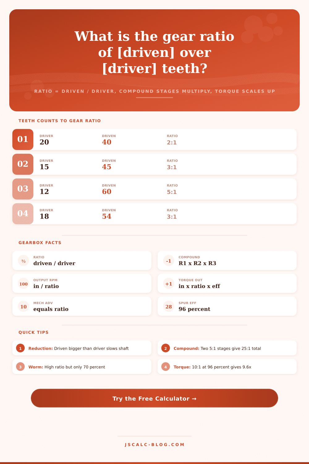
| 20 | 40 | 2.00 | 2:1 reduction |
| 15 | 45 | 3.00 | 3:1 reduction |
| 12 | 60 | 5.00 | 5:1 reduction |
| 16 | 64 | 4.00 | 4:1 reduction |
| 10 | 70 | 7.00 | 7:1 reduction |
| 11 | 88 | 8.00 | 8:1 reduction |
| 40 | 20 | 0.50 | 1:2 overdrive |
| 25 | 50 | 2.00 | 2:1 reduction |
📊Single vs Compound Reduction
| Layout | Stage 1 | Stage 2 | Stage 3 | Total Ratio |
|---|---|---|---|---|
| Single stage | 5:1 | - | - | 5:1 |
| Two stage compound | 5:1 | 5:1 | - | 25:1 |
| Two stage mixed | 4:1 | 3:1 | - | 12:1 |
| Three stage compound | 3:1 | 3:1 | 3:1 | 27:1 |
| Three stage mixed | 4:1 | 3:1 | 3:1 | 36:1 |
| High reduction | 5:1 | 4:1 | 5:1 | 100:1 |
| Winch drive | 6:1 | 6:1 | - | 36:1 |
⚡Ratio to Torque Multiplication
| Ratio | Input Torque | Ideal Output | At 96% Spur | At 70% Worm |
|---|---|---|---|---|
| 2:1 | 10 Nm | 20 Nm | 19.2 Nm | 14.0 Nm |
| 5:1 | 10 Nm | 50 Nm | 48.0 Nm | 35.0 Nm |
| 10:1 | 10 Nm | 100 Nm | 96.0 Nm | 70.0 Nm |
| 25:1 | 10 Nm | 250 Nm | 240 Nm | 175 Nm |
| 30:1 | 10 Nm | 300 Nm | 288 Nm | 210 Nm |
| 50:1 | 10 Nm | 500 Nm | 480 Nm | 350 Nm |
| 100:1 | 10 Nm | 1000 Nm | 960 Nm | 700 Nm |
🗃Gearbox Type Comparison Grid
| Gear Type | Typical Ratio | Efficiency | Noise | Relative Cost | Common Use |
|---|---|---|---|---|---|
| Spur | 1:1 to 8:1 | 94 to 98% | Moderate | Low | Simple drives |
| Helical | 1:1 to 10:1 | 96 to 98% | Low | Medium | Heavy conveyors |
| Worm | 5:1 to 100:1 | 50 to 90% | Very low | Medium | Compact reducers |
| Planetary | 3:1 to 10:1 per stage | 90 to 98% | Low | High | Servo actuators |
| Bevel | 1:1 to 6:1 | 92 to 98% | Moderate | Medium | Right-angle drives |
| Cycloidal | 10:1 to 120:1 | 85 to 93% | Low | High | Robotics, shock loads |
⚙Formula Breakdown
💡Gearbox Selection Tips
The page also includes a gearbox gear ratio calculator that answer two main questions: How much does the gearbox return in torque? How much does the gearbox slow the shaft down? This is the tool that you’d use when building something yourself, or working with an industrial machine where getting more torque requires sacrificing some speed and vice versa. All those gears makes all the difference.
The tool can work out the reduction ratio from both measured output and input speeds or from raw number of teeth on each gear. It will chain together up to three compound stages, and report back the multiplied torque (after accounting for efficiency losses) as well as the output shaft speed in RPM. Built for actual reducer hardware instead of car transmissions, the efficiency figures and presets reflect what you’ll see on factory floor.
How the Gearbox Calculator Works
One gear mesh features a driver gear on its input shaft and a driven gear on the output shaft. To get the gear ratio, divide the number of teeth on the driven (output) by the number on driver (input). Any time the driven gear’s bigger, you’ll have a gear ratio of more then one, meaning the gearbox will reduce speed but increase torque, making it a speed reducer. A three-to-one ratio means a 20-tooth pinion turning a 60-tooth gear. Reverse them (a big driver spinning a small driven), and you’ve got an overdrive where the output spins faster but loses some torque. The calculator does all the math for you after you enter your tooth counts, no need to guess at any conversion or multiplier factors.
An industrial gearbox can’t get its desired ratio with just a couple of gears, at least not ones that aren’t too big. Instead, the solution is a group of gear pairs in a row whose ratios are multiplied. Say one’s five to one, and the next is another five to one; that gives you a total ratio of twenty-five to one. You can select more than one stage. You do this by selecting the arrangement, entering the teeth of the driver and driven gear for each active stage, and letting the tool create the product. That preserves simplicity of a single reduction but lets you add an extra box of stages when needed.
Tachometer, The shaft speeds can be measured with a tachometer when you don’t have the gear covers off and cannot count teeth. If you plug the calculator into speed mode it will calculate the ratio directly (input RPM/output RPM). So if your motor spins at 1750 RPM while your output shaft spins at 175 RPM, your gearbox is turning a ten to one. This is also the quickest way to verify that your installed reducer is what’s on its name plate, or to reverse engineer an unlabeled reducer.
After that, the torque increase math is the same so you still have an estimate of output torque from the input torque you provide. The output speed comes directly from there once you know the overall ratio. If the shaft slows down, that multiplies the twisting force. It is the same as torque, just in reverse. So the ideal torque out is the input torque times the total ratio (no gearbox is perfect though) and the calculator multiplies by the given efficiency for the selected gear type. If you plug in ten Newton meters on a nine to one helical gear with 97 percent efficiency it spits back around eighty-seven Newton meters.
The ideal torque multiplier is the same as the total gear ratio, before losses. That’s what shows up on the mechanical advantage card. But don’t dismiss that little dropdown for efficiency. Helical and spur gears are very efficient, roughly 96 to 98 percent each, which means nearly all the torque benefit comes through. On the other hand, worm gears provide huge gearing ratios in a single compact stage, but they suffer from sliding friction between their worm and wheel. This means they typically operate at just 70 percent or less (with some losing up to 30 percent), which results in wasted energy as heat. Planetary and bevel reducers falls somewhere in the middle of this spectrum.
The output torque estimate will reflect this choice of gear type. The comparison grid gives typical efficiency, noise, cost, and use/rationale for each design type, letting you see the trade-offs at a glance.
A reduction is a mechanical system driven by gear ratio, which drives everything else: output shaft load, motor size and so on. Oversize it, and you waste speed and pay for a larger, heavier reducer than the job needs. Undersize it, and you have too little torque to push your load but your machine is running too fast. This calculator puts realistic efficiency into one place using speed-based and teeth-count based ratios. These ratios let you design a reduction, check an existing gearbox, or predict the output torque without cutting a keyway first.
Start with a preset, then read the four cards to see exactly how the gears turn speed into force and check out the breakdown. It’s a bridge between abstract geometry and practical power. You should of used it earlier.