Compression Ratio Calculator
Find static engine compression ratio from bore, stroke, combustion chamber volume, head gasket, piston deck clearance, and dome or dish, plus swept, clearance, and total displacement.
🎯Real Engine Presets
📝Engine Inputs
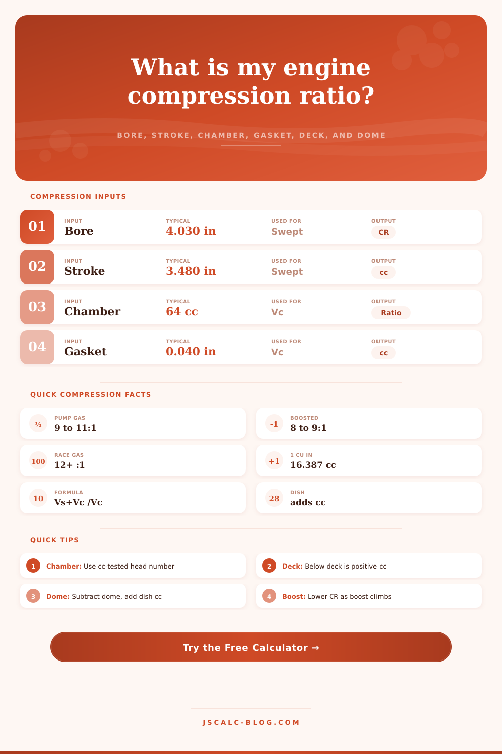
Diameter of the cylinder. 4.030 in is a common 350 bore.
Full piston travel top to bottom.
Use the cc-tested head chamber number.
Gasket opening diameter, usually a touch over bore.
Positive if the piston stops below the deck at TDC.
Dish volume is positive, a dome is negative.
🔢Formula Snapshot
⛽Fuel and Octane Guide
| Combo | Static CR | Fuel / Octane | Notes |
|---|---|---|---|
| Mild NA, iron heads | 8.5 to 9.5:1 | 87 regular | Stock, low quench |
| Street NA, alloy heads | 9.5 to 10.5:1 | 87 to 89 | Good quench helps |
| Performance NA pump | 10.5 to 11.0:1 | 91 to 93 premium | Tight quench, tune |
| Aggressive NA street | 11.0 to 12.0:1 | 93 plus ethanol | Watch timing, heat |
| Boosted low CR | 8.0 to 9.0:1 | 93 or E85 | Lower CR as psi rises |
| Race only | 12.0 to 15.0:1 | Race 100 plus | Leaded or E85 race |
📏Bore and Stroke Displacement Reference
| Engine | Bore (in) | Stroke (in) | Cyl | Displacement |
|---|---|---|---|---|
| Chevy 350 | 4.000 | 3.480 | 8 | 350 cid / 5.7 L |
| Chevy 383 stroker | 4.030 | 3.750 | 8 | 383 cid / 6.3 L |
| GM LS 5.3 | 3.780 | 3.622 | 8 | 325 cid / 5.3 L |
| Chevy 454 BBC | 4.250 | 4.000 | 8 | 454 cid / 7.4 L |
| Honda B18C | 3.189 | 3.465 | 4 | 110 cid / 1.8 L |
| Ford 302 | 4.000 | 3.000 | 8 | 302 cid / 4.9 L |
🔄Volume Conversion Reference
| From | To | Multiply By | Example |
|---|---|---|---|
| Cubic inches | Cubic centimeters | 16.387 | 350 cid = 5735 cc |
| Cubic centimeters | Liters | 0.001 | 5735 cc = 5.74 L |
| Liters | Cubic inches | 61.024 | 5.7 L = 348 cid |
| Inches | Centimeters | 2.540 | 4.030 in = 10.24 cm |
| Millimeters | Centimeters | 0.100 | 96.0 mm = 9.60 cm |
| Cubic centimeters | Cubic inches | 0.061 | 76 cc = 4.64 cid |
🗂Gasket and Deck Effect Comparison Grid
| Scenario | Chamber | Gasket | Deck | Dome / Dish | Static CR |
|---|---|---|---|---|---|
| Baseline 350 | 76 cc | 0.041 in | 0.025 in | +6 cc dish | ~9.3:1 |
| Smaller chamber | 64 cc | 0.041 in | 0.025 in | +6 cc dish | ~10.6:1 |
| Thin gasket | 76 cc | 0.028 in | 0.025 in | +6 cc dish | ~9.6:1 |
| Zero deck | 76 cc | 0.041 in | 0.000 in | +6 cc dish | ~9.8:1 |
| Flat top piston | 76 cc | 0.041 in | 0.025 in | 0 cc | ~9.8:1 |
| Domed piston | 64 cc | 0.041 in | 0.005 in | -8 cc dome | ~12.4:1 |
| Big dish blower | 72 cc | 0.051 in | 0.020 in | +18 cc dish | ~8.5:1 |
⚙Full Formula Breakdown
📋Input Reference Values
| Item | Common Entry | How It Is Used | Ratio Effect |
|---|---|---|---|
| Chamber volume | 50 to 90 cc | Added to clearance volume | Smaller chamber raises CR |
| Gasket bore | Bore + 0.05 in | Sets gasket disc area | Bigger bore adds a little cc |
| Gasket thickness | 0.028 to 0.055 in | Sets gasket volume | Thinner gasket raises CR |
| Deck clearance | 0.000 to 0.040 in | Volume above piston at TDC | Zero deck raises CR |
| Dome or dish | -12 to +20 cc | Adjusts clearance volume | Dome raises, dish lowers CR |
💡Practical Compression Tips
To some people, compression ratio is simply another spec page figure. In reality, it’s at the core of the engine’s breathing system. A proper ratio mean smooth idling, efficiency and power. Miss the mark, even by a tenth, and you could have detonation knock or reduced low-end torque.
Just plug your piston dish (or dome), deck clearance, gasket thickness, chamber volume, bore, and stroke values into the calculator above. It crunches the complicated numbers for you so you don’t have to guess coefficients or do error-prone conversions between centimeter and cubic inch measurement.
Why Compression Ratio Matters
Swept volume consists of bore and stroke which most folks begin with. Swept volume refers to the space the piston travels in. Two engines can has drastically different compression ratios but the same displacement. Clearance volume refers to the space left when the piston is at the absolute highest point of travel. It encompasses things like the layer on a head gasket, the area around the piston rings, and combustion chamber in the head.
Why do you care? For example, if you add 1/4 inch to your deck clearance, you will add volume and drop compression. The same holds true for choosing a larger gasket. So the calculator parses those inputs into digestible components.
For example, it require input of chamber volume in cubic centimeters, typically provided by a stamping on the cylinder head itself or available from the maker’s catalog. The tendency to mix and match aftermarket heads with various chamber volumes will derail builds here. If all other factors remains unchanged, a smaller chamber increases the compression ratio. Most builders overlook the fact that a bigger bore for the head gasket will contribute additional volume. That reduces the intended ratio quietley and without any warning. It’s one of those sneaky little traps that robs performance without making much noise.
The second part of that equation involve piston geometry. For instance, a domed piston reduces the amount of volume in the clearance area, increasing the ratio. While a dish in the piston crown increases it; the dish actualy decreases the clearance volume (think of it as reducing clearance). That’s common with boosted engines, when you desire lower static ratios. Between 8 and 9 to 1, to prevent pre-ignition while under turbocharger boost.
Enter a negative value if your pistons has a dome, or a positive value if they are dished. This also alters the amount of air/fuel being compressed prior to ignition by the spark plug. The static compression is a start but it doesn’t tell the whole story. Valve timing affects how much the compression is actually used.
This is because late closing of the intake allows some of that charge to be forced back out the intake port before ignition. Even higher lift camshafts can decreases the actual compression well below the static compression due to the loss of volume during the overlap period. An aggressive cam in a race engine may have very high statics and not break up. It still loses enough during the overlap period to maintain reasonable cylinder pressures on race fuel. Knowing that will allow you to determine whether you require an additional 0.2 ratio or simply are using the cam profile to do that job for you.
Fuel quality dictates your ceiling for the compression ratio. Typically, pump gas will handle up to about 10 to 11 to 1 if it’s tuned well and there are snug quench areas. Quench is the little space between the head and piston. It scrubs hot gases as they leave the cylinder and also aids flame spread. About 0.035 inches deck height is typically the sweet spot for both mechanical safety and thermal efficiency.
Ratios above 12 to 1 generally requires high octane race fuel or ethanol to keep things cool. And the handy tool includes those general ranges in the reference tables so you can compare where your own build matches more mainstream industry standards.
The art of building an engine is all about making compromises. More power? Great! But more compression means more heat which equals more stress. Thin gaskets increase compression but can leak when machined tolerances slip a bit. No deck? It might look good on paper, but it doesn’t allow for any wear or heat expansion.
Before buying anything or cutting any metal you can run numbers and get an idea what will happen. It turns abstract variables into real possibilities. Seeing the sensitivity of the ratio to tiny shifts in piston profile or gasket thickness causes you to begin measuring twice. When you are trying to squeeze horsepower out of air and fuel instead of simply increasing cubic inches, precision matters.
There are two sides to compression: getting as much juice from each drop of gas and operating safely in that range. How much do you want to squeeze? Enough to produce power, yet not so hard that it knocks on a hot day or requires special race-type gas. Use the compression calculator (above) for the facts needed to make that decision comfortabley.
No guessing required; just select components based off the calculations. Begin with known values and allow equations to drive part choices. This will translate into a functioning motor rather than a heap of steel.