Wire Antenna Length Calculator
Size a half-wave dipole, quarter-wave vertical, or full-wave loop from any frequency. Uses the classic 468 / 234 / 1005 wire formulas with an adjustable velocity (K) factor and metric output.
📡Real Antenna Presets
📝Antenna Inputs
Use the center of your intended range.
Active when the dropdown is set to custom.
🔢Formula Snapshot
📊Frequency vs Length Comparison
| Freq MHz | Dipole ft | Leg ft | Vertical ft | Loop ft | Dipole m |
|---|---|---|---|---|---|
| 1.9 | 246.3 | 123.2 | 123.2 | 528.9 | 75.08 |
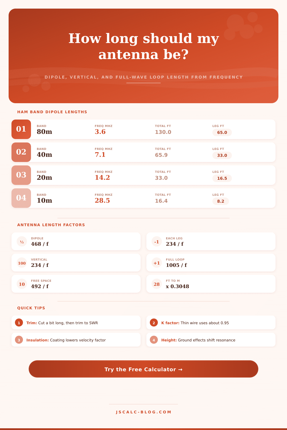
| 3.6 | 130.0 | 65.0 | 65.0 | 279.2 | 39.62 |
| 7.1 | 65.9 | 33.0 | 33.0 | 141.5 | 20.09 |
| 10.125 | 46.2 | 23.1 | 23.1 | 99.3 | 14.09 |
| 14.2 | 33.0 | 16.5 | 16.5 | 70.8 | 10.05 |
| 21.3 | 22.0 | 11.0 | 11.0 | 47.2 | 6.70 |
| 28.5 | 16.4 | 8.2 | 8.2 | 35.3 | 5.01 |
| 52.0 | 9.0 | 4.5 | 4.5 | 19.3 | 2.74 |
| 146.0 | 3.2 | 1.6 | 1.6 | 6.9 | 0.98 |
| 446.0 | 1.05 | 0.52 | 0.52 | 2.25 | 0.32 |
🗂Ham Band Dipole Reference
| Band | Typical Freq | Dipole Total | Each Leg | Common Use |
|---|---|---|---|---|
| 160m | 1.9 MHz | 246.3 ft | 123.2 ft | Top band, night DX |
| 80m | 3.6 MHz | 130.0 ft | 65.0 ft | Regional nets, ragchew |
| 40m | 7.1 MHz | 65.9 ft | 33.0 ft | Day and night workhorse |
| 30m | 10.125 MHz | 46.2 ft | 23.1 ft | Digital and CW only |
| 20m | 14.2 MHz | 33.0 ft | 16.5 ft | Long-haul DX phone |
| 15m | 21.3 MHz | 22.0 ft | 11.0 ft | Daytime DX at solar peak |
| 10m | 28.5 MHz | 16.4 ft | 8.2 ft | Sporadic-E and DX |
📐Antenna Type Formulas
| Antenna Type | Length Formula (ft) | Per Element | Feed Point | Notes |
|---|---|---|---|---|
| Half-wave dipole | 468 / f | 234 / f each leg | Center fed | Balanced, needs balun |
| Quarter-wave vertical | 234 / f | Single radiator | Base fed | Needs radials or ground |
| Full-wave loop | 1005 / f | Perimeter total | Corner or bottom | Quiet, high gain |
| Free-space half wave | 492 / f | 246 / f each half | Reference only | No end effect applied |
⚙Velocity / K Factor Guide
| Conductor | K Factor | Effect on Length | When To Use |
|---|---|---|---|
| Free space (theory) | 1.00 | Longest, 492 / f | Math reference only |
| Thin bare wire | 0.96 | Slightly shorter | Small gauge, high in clear |
| Standard bare copper | 0.95 | Classic 468 / f | Most bare wire dipoles |
| Insulated wire | 0.93 | About 2% shorter | PVC coated antenna wire |
| Thick or coated | 0.90 | Noticeably shorter | Heavy jacket, low height |
💡Full Formula Breakdown
🔧Practical Antenna Tips
So maybe you get frustrated because that first dipole you cut to the textbook’s half-wavelength formula doesn’t quite work like it should. It resonates fifty kilohertz above where you expected; how come? What’s wrong with this book printed out twenty years ago? Why isn’t it matching up to the real world thingy dangled between a couple tree?
Usually it’s velocity factor that cause all the trouble. Velocity factor sounds academic. It sounds like something that belongs on a college physics exam. But really it’s about the resistance in space: how much the electrons has to fight their way through plastic insulation or copper. Or even how much they resist through thin air.
Why Your Antenna Length Is Wrong
There are calculators that will help you size a full-wave loop, quarter-wave vertical, or half-wave dipole at any frequency. They use the classic 468, 234, and 1005 numbers. And there’s also a variable for velocity factor. That’s where you understand why the numbers shifts. This keeps you on the air.
So here’s the thing: Antennas don’t move EM waves along at speed of light in a vacuum. They are slowed by dielectric nature of whatever material coats the wire, plus some extra due to end effects. Because of this, we need to make antenna physically smaller than expected wavelength. Enter the K-factor (or velocity coefficient), which is adjustable within the calculator so that you can input how your hardware actualy performs.
For instance, bare copper wire isn’t going to act the same way as thick, insulated coaxial cable being used as a temporary radiator. Not accounting for this parameter is effectively making a confident guess, a potentially dangerous pairing given that you’ve just stripped thirty feet of expensive wire.
Take one example: How would a quarter-wave vertical compare to a half-wave dipole? While the latter has two legs whose combined length approximates 468 divided by the frequency (in MHz), a quarter-wave vertical is just a quarter wavelength long for the radiator itself, but depends on a radial system of ground radials to complete electrical circuit. This means you divide 234 by the frequency. The tool will allow you to flip from one mode to the other with a click, since a vertical is frequently mounted near a vehicle or house where you have no height. Even though you lose a bit of gain versus a dipole properly elevated, you may want the omnidirections coverage anyway.
A second interesting example is a full-wave loop, which is not only quiet in reception, but also looks like just a random wire wrapped around a pole, ideal if your operating style favors stealth! The formula for a full-wave loop jump to 1005 divided by the frequency to reflect the full wavelength requirement. That’s little enough, but it makes a difference aesthetically and with the zoning board. You can see this laid out nicely in the table on the page, where length increase as you climb from low-frequency HF bands toward VHF.
When practical installation is considered, there are variables beyond what any spreadsheet can account for. The surrounding environment shifts resonance based off how close it is to nearby buildings, metal objects and even height in the ground once the antenna goes up. For this reason, all seasoned hams leave some extra wire when they cut it out. Then use an analyzer to measure the standing wave ratio and trim until the SWR read correctly. It is a tactile process tying theory to practice. It is not simply making something, but tuning a resonant system.
Remember that if you’re using coated antenna wire, or even the standard lamp cord, you must think about the insulation on the wire itself. The velocity factor is reduced; the wave doesn’t travel as fast down the line with that plastic jacket on there. So your antenna’s electrically too long if you figure it out based off bare copper. The tool adjusts for this and trims the recommendation accordingly (selecting a lower K factor). It’s a small adjustment, but it saves you from spending hours forcing an SWR match onto a physically mismatched antenna.
The bottom line with wire antennas is all about compromise. Aesthetics and the amount of space you have matter, along with your desired operating frequency range. If you want to make local net contacts on 2 meters, great. Or if you’re after some DX on 20 meters, great. It’s all the same set of principles. Use the adjusted formulas to get close on basic length, then trim in situ to resonance, and let nature take its course in the real world.
Sometimes less really is more, and the trick isn’t necessarily the wire, but rather knowing exactly what part of that wire would of been doing all the talking.