Wheatstone Bridge Balance Calculator
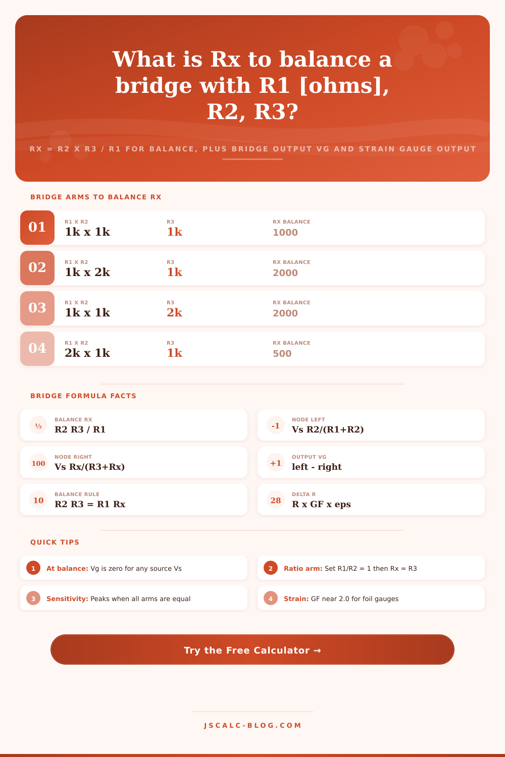
Find the unknown fourth arm that balances a Wheatstone bridge with Rx = R2 x R3 / R1, compute the diagonal output voltage Vg from the two divider nodes, check whether the bridge is balanced or unbalanced with polarity, and model foil strain gauge output from gauge factor and strain.
⚖Choose a Mode
🎯Real Bridge Presets
🔌Bridge Inputs
Excitation across the bridge supply diagonal.
Multiplier applied to R1, R2, R3, and Rx.
Upper resistor of the left divider leg.
Lower resistor of the left divider leg.
Upper resistor of the right divider leg.
Lower right arm. Compared to the balance value.
Strain sensitivity of the foil gauge, near 2.0.
Applied strain in microstrain. 1000 ue = 0.001.
Controls rounding on every result card.
🔢Formula Snapshot
📋Bridge Arms to Balance Rx
| R1 | R2 | R3 | Rx = R2 R3 / R1 | Reads As |
|---|---|---|---|---|
| 1 k | 1 k | 1 k | 1000 | Equal arms |
| 1 k | 2 k | 1 k | 2000 | Double Rx |
| 2 k | 1 k | 1 k | 500 | Half Rx |
| 1 k | 1 k | 2 k | 2000 | Double Rx |
| 10 k | 10 k | 10 k | 10000 | Precision |
| 330 | 330 | 330 | 330 | Strain arm |
| 120 | 120 | 120 | 120 | Foil gauge |
| 100 | 200 | 100 | 200 | 2:1 ratio |
| 470 | 680 | 330 | 477.4 | Odd values |
| 1 k | 1 k | 350 | 350 | Load cell |
📏Strain Gauge Bridge Configurations
| Configuration | Active Arms | Relative Output | Temp Comp | Typical Use |
|---|---|---|---|---|
| Quarter bridge | 1 of 4 | 1x baseline | Limited | Single point strain |
| Half bridge bending | 2 opposite | 2x baseline | Good | Beam bending |
| Half bridge axial | 2 with Poisson | 1.3x approx | Good | Axial load |
| Full bridge bending | 4 active | 4x baseline | Full | Load cells |
| Full bridge axial | 4 active | 2.6x approx | Full | Column force |
| Diagonal bridge | 2 diagonal | 2x baseline | Good | Torque shafts |
📈Common Sensor Gauge Factors
| Sensor Type | Gauge Factor | Nominal Ohm | Note |
|---|---|---|---|
| Constantan foil | 2.0 | 120, 350 | Standard workhorse |
| Karma alloy foil | 2.1 | 350, 1000 | Wide temperature |
| Platinum tungsten | 4.0 | 350 | High output foil |
| Semiconductor P | 100 to 170 | 540 | Very high, nonlinear |
| Semiconductor N | -100 to -140 | 540 | Negative response |
| Nichrome thin film | 2.0 | 1000 | Sputtered sensors |
🗃Bridge Output Comparison Grid
| R1 | R2 | R3 | Rx | Vg at Vs 5V | State |
|---|---|---|---|---|---|
| 1000 | 1000 | 1000 | 1000 | 0 mV | Balanced |
| 1000 | 1000 | 1000 | 1010 | -12.4 mV | Rx high |
| 1000 | 1000 | 1000 | 990 | 12.6 mV | Rx low |
| 1000 | 1000 | 1000 | 1100 | -119 mV | Rx high |
| 1000 | 1000 | 1000 | 1050 | -61.0 mV | Rx high |
| 350 | 350 | 350 | 350.7 | -2.5 mV | 1000 ue |
| 120 | 120 | 120 | 120.24 | -2.5 mV | 1000 ue |
| 10000 | 10000 | 10000 | 10000 | 0 mV | Balanced |
| 2000 | 1000 | 1000 | 500 | 0 mV | Balanced |
| 1000 | 2000 | 1000 | 1500 | 66.7 mV | Rx low |
⚙Formula Breakdown
💡Wheatstone Bridge Tips
On paper, the Wheatstone bridge looks straightforward, but as always, good engineering matter. Essentially, it’s a pair of voltage dividers connected in parallel, but that simple design was standard method for measuring resistance years before digital multimeters arrived.
What this calculator does is perform two calculation: (1) determine what resistance value will cause the bridge to “go null” and (2) calculate resulting voltage across the bridge with mismatched arms. This is useful if you’re working on interfacing sensor, where a tiny difference in arm values matches an expected output voltage. It is also useful for situations where you want to create a high-accuracy null measurement.
How to Use the Wheatstone Bridge Calculator
Here’s basic principle. Put a source voltage across two resistors (called legs). Split this voltage between R1 and R2 with the left leg and split the same voltage between R3 and the other unknown resistor arm Rx with the right leg. Place an output at the midpoint of each leg. When balanced, the leg ratios is equal and the midpoints will have same potential. There will be no current flowing diagonal through the circuit. That is the balance point.
It’s called a null measurement, meaning that instead of reading some particular voltage value, you’re seeking zero. It’s a very robust method that doesn’t rely on having a calibrated meter, nor an absolutely stable power supply. That means to find that balance point, you solve for Rx as (R2 x R3)/R1.
With this relationship, the tool quickly calculates it for you, eliminating the need to re-do the math each time you adjust one of arms. Setting both ratio arms (R1 and R2) to the same value neatly simplifies equation. In this case, Rx become just R3. It’s easier to get it right, which is a big plus. And since the whole thing is symmetrical, it intuitively feels correct too. A lot of high-precision bridges use carefully matched resistor networks precisely to maintain this ratio.
The bridge isn’t usually nulled out anymore. We let it remain a little bit off-balance intentionaly. A thermistor or strain gauge is a type of sensor whose resistance change based on some sort of physical force. As its resistance changes, that disturbs the balance and generates a tiny voltage between two point on the diagonal. The calculator does this math by finding the nodal voltages and then subtracting them from each other. It will tell you exactly what number of millivolts to expect for any particular change in Rx.
This is key if you’re designing an amplifier. Maybe the sensor doesn’t move the bridge output very far, maybe just by five millivolts? You’ll need an amplifier that has sufficient gain so that you get something out of that input without also taking in a bunch of noise. In this case sensitivity is more important then just accuracy.
All four of the arms should be approximately equal. That way they form a voltage divider whose slope are steepest. If one is ten ohms and the other ten thousand, the slope flattens. Resolution suffers. This is where the tool explains the trade off well. When you adjust the inputs, you see how moving away from an even ratio decreases the voltage swing for the same percent change in resistance. A small thing but that determines the signal to noise ratio.
This is what a strain gauge does. It’s the most popular application. When it’s stretched or compressed, very slightly, it will change its resistance. Enter the microstrains and the gauge factor into the calculator in strain mode to get the corresponding voltage. With a typical foil gauge, the gauge factor is around 2.0. So if you stretch the gauge a thousand times more than your starting length (called one thousand microstrain), it will change its resistance by two tenths of a percent. In ohms on a three hundred fifty ohm bridge, that’s less than one ohm. But the bridge converts that fractional ohm change into a millivolt signal we can measure.
But then there’s the matter of a quarter, half, or full bridge. With a quarter-bridge configuration, you have an active sensor plus three fixed resistors. That’s fine, but it’s not very good at temperature compensation. Full bridge? It uses four active sensors to add their changes up. The output will be about four times as large, and temperature drift will pretty much cancel each other out. This is why load cells are all full bridges. You want them to be as sensitive and stable as possible.
Four active sensors for adding their changes up. The output will be about four times as large, and temperature drift will pretty much cancel each other out. This is why load cells are all full bridges. You want them to be as sensitive and stable as possible.
There are a few reference tables in the middle of the page that serve as a cheat sheet when looking up common setups. For example, you might wonder what combination of material and gauge works best, or how an arm value will impact the balance point. These make it nice to have side-by-side with the live calculation so you know if a two millivolt per volt output is realistic or not.
When you’re rushing, or perhaps just tired, bridge arithmetic is prone to error. Calculating ratios incorrectly causes large miscalculation of sensor readings. A spot to check the balance condition and estimate the resulting unbalanced voltage eliminates wasted time. You should of checked this earlier. Try resistors at various values without purchasing them first. Ensure that the maximum expected voltage swing fits within the input range of your amplifier. Turn theoretical circuits into practical design choices.
In conclusion, the Wheatstone bridge is still useful today because of its simple beauty. It translates resistance changes to voltage in a simple way. This works whether you are connecting a complex force sensor or trying to measure one unknown resistor. The math stays the same, and the tool simply takes care of the drudgery for you. A few variables in an equation become a clear image of what’s happening in your circuit when it’s loaded, and that insight is worth something.