Series Capacitance Calculator
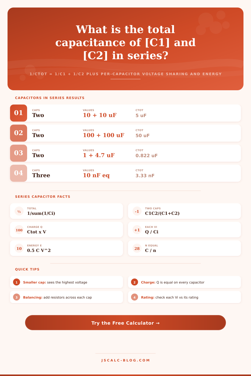
Combine capacitors in series with 1/Ctot = 1/C1 + 1/C2 + ..., see how the total drops below the smallest capacitor, and get the equal charge Q, the voltage across each capacitor Vi = Vtot x Ctot / Ci, and the energy stored E = 0.5 x Ctot x V squared. The calculator flags the capacitor under the highest voltage stress.
🎯Real Series Capacitor Presets
🔌Series Capacitor Inputs
More capacitors in series lower the total further.
Applies to every capacitor value C1 to C5.
First capacitor in the series string.
Second capacitor in the series string.
Shown when 3 or more capacitors are selected.
Shown when 4 or more capacitors are selected.
Shown when 5 capacitors are selected.
DC voltage across the whole series string.
Controls rounding on every result card.
🔢Formula Snapshot
📋Why Series Lowers Capacitance
| Equal Caps | Count n | Ctot = C / n | Reads As |
|---|---|---|---|
| 100 uF | 2 | 50 uF | Half the value |
| 100 uF | 3 | 33.3 uF | One third |
| 100 uF | 4 | 25 uF | One quarter |
| 100 uF | 5 | 20 uF | One fifth |
| 10 nF | 2 | 5 nF | Half the value |
| 10 nF | 3 | 3.33 nF | One third |
| 1 uF | 4 | 0.25 uF | One quarter |
| 1 uF | 5 | 0.2 uF | One fifth |
⚖Voltage Sharing Between Two Caps
| C1 | C2 | V1 share | V2 share | Note |
|---|---|---|---|---|
| 100 uF | 100 uF | 50% | 50% | Equal split |
| 1 uF | 4.7 uF | 82.5% | 17.5% | Small sees more |
| 1 uF | 10 uF | 90.9% | 9.1% | Small sees more |
| 100 pF | 47 pF | 32.0% | 68.0% | Small sees more |
| 10 nF | 22 nF | 68.8% | 31.2% | Small sees more |
| 220 nF | 220 nF | 50% | 50% | Equal split |
| 2.2 uF | 1 uF | 31.3% | 68.8% | Small sees more |
📏Standard Capacitor Decade Values
| E6 Value | Picofarads | Nanofarads | Microfarads |
|---|---|---|---|
| 1.0 | 100 pF | 1 nF | 1 uF |
| 1.5 | 150 pF | 1.5 nF | 1.5 uF |
| 2.2 | 220 pF | 2.2 nF | 2.2 uF |
| 3.3 | 330 pF | 3.3 nF | 3.3 uF |
| 4.7 | 470 pF | 4.7 nF | 4.7 uF |
| 6.8 | 680 pF | 6.8 nF | 6.8 uF |
| 10 | 1000 pF | 10 nF | 10 uF |
🗃Two-Cap Series Comparison Grid
| C1 | C2 | Ctot | Q at 50 V | V1 | V2 |
|---|---|---|---|---|---|
| 100 uF | 100 uF | 50 uF | 2.5 mC | 25 V | 25 V |
| 1 uF | 4.7 uF | 0.822 uF | 41.1 uC | 41.2 V | 8.8 V |
| 1 uF | 10 uF | 0.909 uF | 45.5 uC | 45.5 V | 4.5 V |
| 100 pF | 47 pF | 31.97 pF | 1.6 nC | 16.0 V | 34.0 V |
| 10 nF | 22 nF | 6.875 nF | 0.344 uC | 34.4 V | 15.6 V |
| 220 nF | 220 nF | 110 nF | 5.5 uC | 25 V | 25 V |
| 2.2 uF | 1 uF | 0.688 uF | 34.4 uC | 15.6 V | 34.4 V |
| 470 pF | 470 pF | 235 pF | 11.75 nC | 25 V | 25 V |
| 10 uF | 10 uF | 5 uF | 250 uC | 25 V | 25 V |
| 1 nF | 1 nF | 0.5 nF | 25 nC | 25 V | 25 V |
⚙Formula Breakdown
💡Practical Series Capacitor Tips
If you’re accustomed to working with resistors, wiring capacitors in series seems…wrong. When you put resistors end to end, they adds up linearly. Capacitators? No way, they go the other direction. The total capacitance becomes less then the smallest one in the string. This is counterintuitive. It is enough to trip up beginners and infuriate engineers looking for bigger storage capacity.
Once you know values you need, just plug them into calculator above and it’ll do the math for you, saving you the reciprocal sums in your head. And it’ll even handle bits that really count for safety in a circuit. It handles the voltage stress on each capacitor individually, as well as how charge distributes across all the caps.
How Capacitors Work in Series
It’s all based off reciprocals. The equation that governs depends on them. To calculate the combined value, you add together one over every capacitance value and then you take one over that sum. So mathematically, adding more capacitors in series will always reduce total. If you have two of the same cap, you get half the original value. If you have three, you gets a third, and so on. Capacitance does not accumulate.
That is why you do not usually see people stacking capacitors to create smaller capacitance values. They do it to withstand higher voltages. A given capacitor might only be rated at twenty volts, but if you put two in series they can handles forty if the voltage splits evenly between them. That is why the setup matter.
That’s where it begins to get dicey: Voltage Sharing. Ideally, if components were exactly alike, the voltage divides equally. But real caps are not alike. Each has a different leakage current. Each have different tolerances. When fifty volts is applied between two caps, 1 uF and 10 uF in series, neither gets an equal load. The larger cap get five volts while the smaller cap gets about forty-five.
The calculator notes difference by coloring the highest stressed voltage for you. That way you know what component to compare against ratings. You will find out when the overstressed cap burns up, sending the whole line voltage to the others until they also fail.
The solution to this problem is what engineers call “balancing resistors.” On every capacitor in the string, a large value resistor is installed in parallel with it. They act as load on all the capacitors so that even if they leak differently from one another, the DC voltage splits equally. They are small but important to prevent total disaster.
You can enter several capacitors into the tool and see clearly how the voltage splits among them. Change the number, change their values, watch how the stress moves around. That’s good when building something like a high-voltage filter or snubber network where reliability simply cannot be compromised.
The total string of capacitors have the same amount of charge. All of them passed the same current while charging, and so they all has the same charge. That charge divided by the capacitance of unit gives you the voltage drop per unit. The lower the capacitance the more voltage (for the same amount of charge).
That’s a trade off. Higher voltage headroom means less storage capacity. More voltage, less storage capacity. It has less total energy storage than one larger capacitor at the same voltage. You’re paying for the insulation distance with the storage space.
There are preset buttons that provide fast reference points. Test a mixed value tuning circuit. Load two 100 microfarad caps and double your working voltage. These are some of the example scenarios shown here. Unequal values skews the results immediately. Before you even think about soldering it’s good to get in there and run a couple of simulations.
That understanding of where the voltage is concentrating and why the total drops out will turn a confusing formula into a practical design tool. Series strings then becomes a robust solution to high-voltage applications rather than a ticking time bomb if you have the correct balancing measures in place.