Parallel Capacitance Calculator
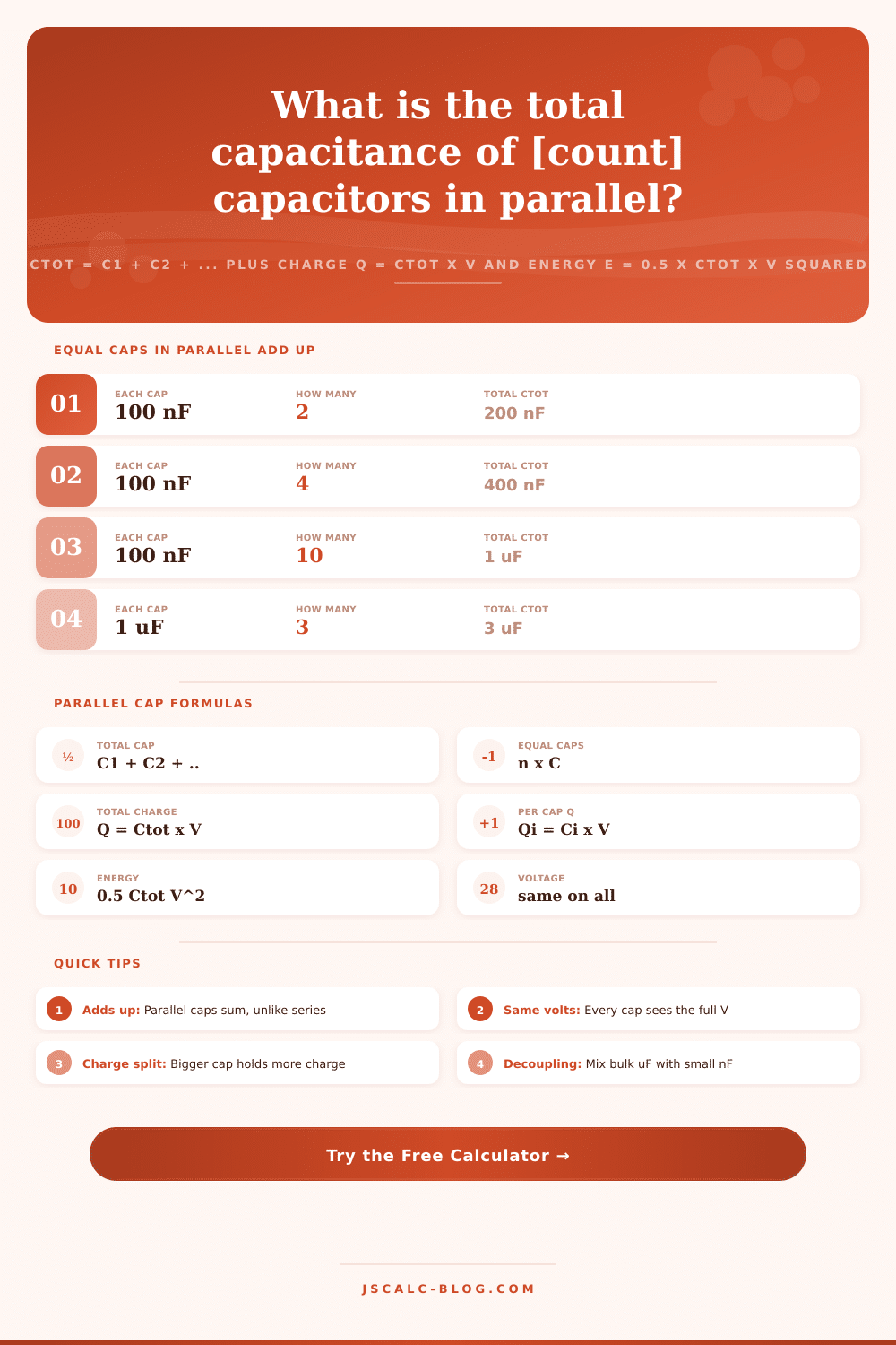
Add two to five capacitors wired in parallel to find the total capacitance with Ctot = C1 + C2 + ..., then get the total charge Q = Ctot x V, the charge stored in each individual capacitor Qi = Ci x V, and the total energy E = 0.5 x Ctot x V squared. Every capacitor in parallel sees the same voltage while their capacitances simply add.
🎯Real Parallel Capacitor Presets
🔌Capacitor Inputs
Choose how many branches are wired in parallel; fields C1 to C5 show accordingly.
All C1 to C5 entries use this same unit.
First capacitor, in the unit selected above.
Second capacitor, same unit.
Third capacitor, shown when count is 3 or more.
Fourth capacitor, shown when count is 4 or more.
Fifth capacitor, shown when count is 5.
In parallel every capacitor sees this same voltage.
Controls rounding on every result card.
🔢Formula Snapshot
➕Equal Capacitors in Parallel
| Each Capacitor | How Many | Total Ctot = n × C | Reads As |
|---|---|---|---|
| 100 nF | 2 | 200 nF | 0.2 uF |
| 100 nF | 4 | 400 nF | 0.4 uF |
| 100 nF | 10 | 1000 nF | 1 uF |
| 1 uF | 3 | 3 uF | 3 microfarad |
| 10 uF | 5 | 50 uF | 50 microfarad |
| 470 uF | 2 | 940 uF | near 1 mF |
| 1000 uF | 3 | 3000 uF | 3 mF |
| 22 pF | 2 | 44 pF | 44 picofarad |
📋Charge Distribution Across Branches
| Branch Cap | Voltage | Charge Qi = Ci × V | Share of Total | Note |
|---|---|---|---|---|
| 1000 uF | 12 V | 0.012 C | 50 percent | Half of a 2x bank |
| 1000 uF | 12 V | 0.012 C | 50 percent | Other half |
| 470 uF | 12 V | 0.00564 C | Smaller share | Less charge, same V |
| 100 uF | 12 V | 0.0012 C | Tiny share | Small branch |
| 10 uF | 12 V | 0.00012 C | Minor share | Bypass class |
| 100 nF | 12 V | 1.2e-6 C | Negligible | Decoupling |
🔧Standard Capacitor Decade Values
| Class | Typical Values | Unit | Common Use |
|---|---|---|---|
| Small ceramic | 10, 22, 47, 100 | pF | Timing, RF tuning |
| Ceramic decouple | 1, 10, 100 | nF | IC bypass, snubbers |
| Film and MLCC | 0.1, 1, 10 | uF | Filtering, coupling |
| Electrolytic bulk | 100, 470, 1000 | uF | Rail smoothing |
| Big electrolytic | 2200, 4700 | uF | Amplifier reservoirs |
| Supercapacitor | 0.1, 1, 10 | F | Backup, hold-up |
🗃Two-Cap Parallel Comparison Grid
| C1 | C2 | Ctot | Q1 at 12 V | Q2 at 12 V | Energy at 12 V |
|---|---|---|---|---|---|
| 1000 uF | 1000 uF | 2000 uF | 0.012 C | 0.012 C | 0.144 J |
| 1000 uF | 470 uF | 1470 uF | 0.012 C | 0.00564 C | 0.1058 J |
| 470 uF | 470 uF | 940 uF | 0.00564 C | 0.00564 C | 0.06768 J |
| 220 uF | 220 uF | 440 uF | 0.00264 C | 0.00264 C | 0.03168 J |
| 100 uF | 10 uF | 110 uF | 0.0012 C | 0.00012 C | 0.00792 J |
| 10 uF | 10 uF | 20 uF | 0.00012 C | 0.00012 C | 0.00144 J |
| 1 uF | 1 uF | 2 uF | 1.2e-5 C | 1.2e-5 C | 0.000144 J |
| 100 nF | 100 nF | 200 nF | 1.2e-6 C | 1.2e-6 C | 1.44e-5 J |
| 22 pF | 22 pF | 44 pF | 2.64e-10 C | 2.64e-10 C | 3.168e-9 J |
⚙Formula Breakdown
💡Parallel Capacitor Design Tips
Capacitor add-in math seems like it would be easy; just plug numbers into a formula, done. But wiring them up one way or another make a huge difference in what happens. Is it in series? The effect of multiple caps is reduced as if each were a skinny pipe attached at its ends. Are they parallel? They’re stacked up like plates inside a drawer, increasing overall capacity. That’s the scenario this calculator covers: adding components whose capacitance simply adds up to increase total capacity when all are exposed to the same voltage. On paper, it’s a piece of cake; in real life, knowing where energy gets stored and how charge flows around your branches matter for getting the thing working correctly.
Why Parallel Capacitors Add Up It is about geometry. That’s the core part of why capacitors wired in parallel add together. Basically capacitance represent how much surface area (to store charge) there is for a given amount of voltage. By wiring them next to each other, you’re actualy creating a giant virtual capacitor out of the combined plate areas. Two 1000 microfarad caps becomes 2000 microfarads.
Why Capacitors Add Up When Wired in Parallel
In a parallel connection, total voltage is the same as each part. This is very different than a series connection, where the voltage is divided between each link, making the total voltage less then any single component. In short: parallel is the only answer if you want to get higher storage, or lower impedance for high frequency noise.
This brings us to the second key consideration: Voltage equality. Each branch shares the same two nodes, so each sees the same potential difference between those two points. You can’t parallel wire with different voltage ratings, each capacitor has to have a rating equal to overall voltage of the system. In other words, if your rail is 12 volts, every element in that bank must be able to handle 12 volts without being damaged. That’s why there’s only one voltage input for the calculator, which it uses to calculate amount of energy waiting in the bank and amount of charge it holds. It breaks out the contribution from each individual branch but treats the whole as a single unit when making overall calculation, which keeps view simple.
This leads to a surprising thing: Charge is distributed proportionally. Unless your capacitors are all exactly the same, the charge won’t distribute equally. Because bigger capacitors provides more surface area for charge to sit upon, they’ll tend to get most of it. If you have a 10 microfarad capacitor in parallel with a 1000 microfarad capacitor, the latter will hold about 99 percent of the total charge just due to size! That’s why when the tool displays the charge share for each branch, it shows you what’s getting the lion’s share of the charge and what’s along for the ride to help out just a bit. You can quickly see where adding that small ceramic cap into the mix alongside your big electrolytic bank hardly affects total charge but makes whole thing perform much better at high frequency.
That squared voltage term plays a big role here for energy storage. It’s one-half times voltage squared times capacitance, which means increasing the rail voltage stores much more energy than increasing the capacitance. Raising the capacitance doubles the energy, but the voltage is squared, so doubling it quadruples the energy. That quadratic relationship is also what makes these high-voltage systems capable of storing such impressive amounts of energy despite having relatively small capacitors. The calculator reports this value in joules. This gives you a good idea of how long this bank would keep a load going during a momentary power dip, or how much heat would be released during a sudden discharge.
In the real world, there’s no single size for all components. You use a big electrolytic capacitor for storing lots of energy, and you use little ceramic capacitors for fast transient response. They work together to create a wideband filter that reduces hum at low frequencies and interference at megahertz levels. The small ones respond immediately to a spike of current produced by fast digital switches, while the bigger ones deals with more sustained currents. That’s why the tool has a set of different sized capacitors that it shows in its presets, where it combines 100 microfarad electrolytics, 10 microfarads of film caps, and 100 nanofarad ceramics to make a sturdy power network. You should of seen how much better they work together.
These dynamics make an otherwise trivial addition problem something powerful. This lets you engineer a circuit that handles charge flow, filters out voltage spikes, and regulates power flow. And if you know what fraction of total charge/energy/capacitance comes from each branch, you can create circuits that are not only more reliable, but also more efficient. Next time you wire up some capacitors in parallel (side-by-side), think about it: They’re teammates, all connected at the same voltage, each taking on its own share of the load based off its speed and size.