Voltage Divider Resistor Ratio Calculator
Design a resistive divider from a target output. Enter Vin and Vout to get the required R1/R2 ratio, hold one resistor fixed to find the other, then snap both to the nearest E12, E24, or E96 standard values and see the actual Vout and error you will really get on the bench.
⚡Real Divider Design Presets
📡Divider Design Inputs
Supply feeding the top of the divider.
Voltage you want at the R1 to R2 tap. Must be below Vin.
Pick the resistor you already have; the other is computed.
Value of the resistor chosen above, in the unit below.
Applies to the fixed value and every reported resistance.
Standard grid used to snap both resistors.
Used to flag if the standard resistors draw too much. Leave 0 to skip.
Controls rounding on the result cards.
🔢Divider Formula Snapshot
📋E-Series Standard Values (one decade)
| Series | Tolerance | Values per Decade | Sample Base Values |
|---|---|---|---|
| E6 | 20% | 6 | 1.0 1.5 2.2 3.3 4.7 6.8 |
| E12 | 10% | 12 | 1.0 1.2 1.5 1.8 2.2 2.7 ... |
| E24 | 5% | 24 | 1.0 1.1 1.2 1.3 1.5 1.6 ... |
| E48 | 2% | 48 | 1.00 1.05 1.10 1.15 ... |
| E96 | 1% | 96 | 1.00 1.02 1.05 1.07 ... |
| E192 | 0.5% | 192 | 1.00 1.01 1.02 1.04 ... |
📏Common Target Voltage Ratios
| Vin | Vout | R1 / R2 Ratio | Vout / Vin | Typical Use |
|---|---|---|---|---|
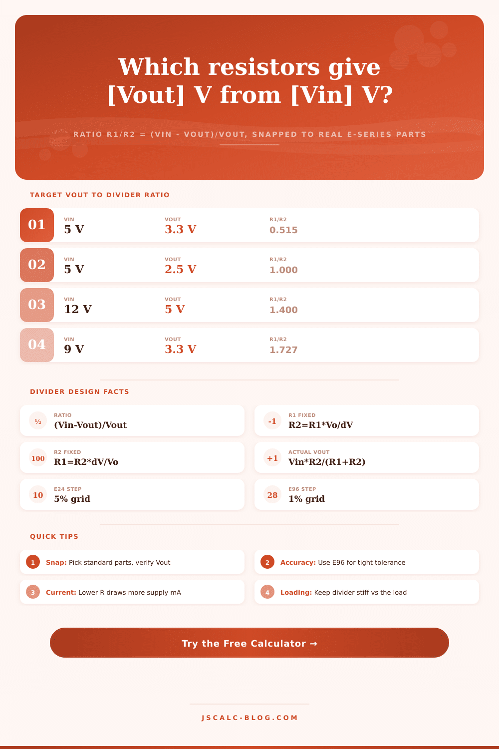
| 5 V | 3.3 V | 0.515 | 0.660 | 5V to 3.3V logic sense |
| 5 V | 2.5 V | 1.000 | 0.500 | Half of 5V reference |
| 3.3 V | 1.65 V | 1.000 | 0.500 | Midpoint bias |
| 12 V | 5 V | 1.400 | 0.417 | 12V rail monitor |
| 9 V | 3.3 V | 1.727 | 0.367 | 9V battery sense |
| 12 V | 3.3 V | 2.636 | 0.275 | ADC feedback |
| 24 V | 3.3 V | 6.273 | 0.138 | 24V bus sense |
| 5 V | 1.8 V | 1.778 | 0.360 | 1.8V level shift |
🗃Design Comparison Grid (fixed R, E24 snap)
| Vin | Vout | Fixed R | Computed Other R | Nearest E24 | Actual Vout |
|---|---|---|---|---|---|
| 5 V | 3.3 V | R2 = 10 k | R1 = 5.15 k | R1 = 5.1 k | 3.311 V |
| 12 V | 5 V | R2 = 10 k | R1 = 14.0 k | R1 = 13 k | 5.217 V |
| 9 V | 2.5 V | R2 = 10 k | R1 = 26.0 k | R1 = 27 k | 2.432 V |
| 3.3 V | 1.65 V | R2 = 10 k | R1 = 10.0 k | R1 = 10 k | 1.650 V |
| 24 V | 3.3 V | R2 = 10 k | R1 = 62.7 k | R1 = 62 k | 3.333 V |
| 12 V | 3.3 V | R1 = 22 k | R2 = 8.34 k | R2 = 8.2 k | 3.257 V |
| 5 V | 1.8 V | R2 = 10 k | R1 = 17.8 k | R1 = 18 k | 1.786 V |
| 15 V | 5 V | R2 = 10 k | R1 = 20.0 k | R1 = 20 k | 5.000 V |
⚙Formula Breakdown
💡Divider Design Tips
Voltage dividers are simple things: they’re just two resistors in series that reduce a high voltage to a low one. A well-designed divider is not determined by picking two resistors and seeing what happens; instead, choose your input voltage, choose your target output value, and work backwards. This tool does all those for you. Just enter your input rail and desired output and it’ll tell you exactly what the ratio should be, which specific resistor to use if you have one lying around, what the closest standard values are that you can buy from distributors, and exactly how far off you’ll be on the bench.
First there’s the ratio, because it’s simply physics. With just a pair of resistors and no load on them, divider’s output has nothing to do with absolute value of those resistors, but everything to do with their relative values. For any division, R1/R2 = (Vin, Vout)/(Vout). So for a 5 volt-to-3.3 volt step-down, the equation boils down to approximately 0.515. That’s the whole electrical design in a nutshell. It tells you that R1 should be approximately half the value of R2. Whether the input is 5.1 kilohms across 10 kilohm or 51 ohms across 100 ohms doesn’t matter at all; the tapped voltage will always be the same. The scale is arbitrary, except when you’re ready to make something out of it.
How to Use the Voltage Divider Tool
Magnitude is up to you; only the ratio matters. To make it easy, you might lock down one of the resistors with something you’ve got lying around. For example, if you decide to fix R2, you can find R1 by multiplying required ratio by R2. With a 3.3 volt step down from 5 volts, fixing R2 at 10 kilohms makes the ideal value for R1 5.15 kilohms. The calculator does that math in a flash. And you can play either side of the equation, changing which resistor you’re keeping constant, and watch how its mate adjusts. That sort of flexibility comes in handy when you’re matching what’s on hand or scavenging through old boards. It also translates an abstract relationship into real-world terms (a shopping list).
Almost none of the partner value is available off the shelf; it is just a specific number. When buying resistors, we’re using things made as part of an E-series grid of decade standard values. If you want common 5 percent values (E24), or cheaper 10 percent ones (E12), you get what’s available. Precision 1 percent parts (E96) comes with many more options. That’s why when you pick a series (which E-series? Since E96 has much better options than E12, the tool will snap your resistors to the closest one available. Often this reduces the discrepancy from your desired voltage a lot. It closes the gap between ideal world and the real world.
Once you pin those two resistors in place as standard values, the real-world value produced never exactly equals what was targeted. To account for this discrepancy, it’s important to check your work. The calculator recalculates the actual voltage based on the standard parts you’ve chosen. When you use a standard 5.1 kilohm top resistor with a 10 kilohm bottom one on a 5 volt rail, you land somewhere in between: at 3.311 volts instead of perfectly 3.3 volts. From there we compute the percent error. That number up-front gives you a quick way to tell if your sensor can get away with a cheap E24 pair. It also tells you if your design will need to specify tighter E96 parts before you reach for soldering iron.
Each calculation is shown on one of four cards. These cards display the fixed resistor’s needed ratio and its exact calculated value, the closest standard pair and its resulting voltage, and the output error as a signed percent. A panel below breaks down all the numbers used in substitution, starting at the ratio, moving through the snapped components, and ending up with the amount of current the divider will draw off the supply. Why should you care? Because the string’s total waste of power depends on absolute resistance values. A 1 kilohm pair gobbles up ten times more battery than does a 10 kilohm pair, which burns only a fraction of a milliamp at 5 volts. The field for max current is an optional feature to flag any standard pair above your ceiling setting, keeping you from accidently draining the battery.
Real designs are loaded into pre-sets that engineers regularly use. Bias points (e.g. Making a half-supply with E96 precision), voltage dividers (e.g. These include voltage dividers, such as stepping 12 volts down to 5 volts on the E24 grid, and references. This includes sensing a 9 volt battery against a 2.5 volt reference. The form is filled out and recalculated instantly. So you can view the entire worked design in one click.
Designing by ratio cleanly separates out the clean math from the messy reality of stock parts. The ideal relationship comes from the ratio. The scale is set by fixed resistor. It’s built using the E-series snap. The error metric will tell you whether to refine components or ship the board.