Voltage Divider Output Calculator
Find the unloaded output of a two-resistor divider from your supply and resistor values. Enter Vin, the top resistor R1 and the bottom resistor R2 and get Vout = Vin x R2 / (R1 + R2), the divider current, the power dissipated in each resistor and the R2/(R1+R2) ratio, with optional tolerance bands.
🎯Real Divider Presets
🔌Divider Inputs
Voltage applied across the whole R1 + R2 string.
Applies to both R1 and R2 fields below.
Between Vin and the output node.
Between the output node and ground. Vout is taken here.
Sets the Vout min and max spread. Use 0 for ideal.
Toggles the resistor power lines in the breakdown.
🔢Formula Snapshot
📋Common Divider Ratios
| R1 | R2 | Ratio R2/(R1+R2) | Vout at 5V Vin |
|---|---|---|---|
| 10 kohm | 10 kohm | 50.0 % | 2.500 V |
| 10 kohm | 20 kohm | 66.7 % | 3.333 V |
| 20 kohm | 10 kohm | 33.3 % | 1.667 V |
| 10 kohm | 1 kohm | 9.09 % | 0.455 V |
| 1 kohm | 10 kohm | 90.9 % | 4.545 V |
| 10 kohm | 3.3 kohm | 24.8 % | 1.241 V |
| 4.7 kohm | 4.7 kohm | 50.0 % | 2.500 V |
| 2 kohm | 1 kohm | 33.3 % | 1.667 V |
📏Standard E24 Resistor Values
| Base Values (x1, x10, x100...) | Common Decade | Typical Use |
|---|---|---|
| 1.0, 1.1, 1.2, 1.3 | 1k, 10k, 100k | Low-side taps |
| 1.5, 1.6, 1.8, 2.0 | 1.5k, 18k, 200k | Bias networks |
| 2.2, 2.4, 2.7, 3.0 | 2.2k, 27k, 220k | ADC scaling |
| 3.3, 3.6, 3.9, 4.3 | 3.3k, 39k, 330k | Feedback taps |
| 4.7, 5.1, 5.6, 6.2 | 4.7k, 51k, 470k | General purpose |
| 6.8, 7.5, 8.2, 9.1 | 6.8k, 82k, 680k | High-side legs |
📊Vin, R1 and R2 to Vout Comparison Grid
| Vin | R1 | R2 | Vout | Current | Total Power |
|---|---|---|---|---|---|
| 5 V | 10 kohm | 10 kohm | 2.500 V | 0.250 mA | 1.25 mW |
| 5 V | 1 kohm | 2 kohm | 3.333 V | 1.667 mA | 8.33 mW |
| 12 V | 10 kohm | 3.3 kohm | 2.977 V | 0.902 mA | 10.83 mW |
| 3.3 V | 10 kohm | 10 kohm | 1.650 V | 0.165 mA | 0.545 mW |
| 9 V | 4.7 kohm | 1.2 kohm | 1.831 V | 1.525 mA | 13.73 mW |
| 24 V | 19 kohm | 5 kohm | 5.000 V | 1.000 mA | 24.00 mW |
| 5 V | 2 kohm | 1 kohm | 1.667 V | 1.667 mA | 8.33 mW |
| 12 V | 8.2 kohm | 2.2 kohm | 2.534 V | 1.152 mA | 13.83 mW |
| 3.3 V | 22 kohm | 33 kohm | 1.980 V | 0.060 mA | 0.198 mW |
| 4.2 V | 100 kohm | 100 kohm | 2.100 V | 0.021 mA | 0.088 mW |
⚙Formula Breakdown
💡Divider Design Tips
Alright, I’ve got this five-volt logic signal that I need to tap into a three point three volt microcontroller input pin. What do I do? Well, I need a middleman of some kind, but I don’t want to spend money on level shifter for a single project. Enter: the voltage divider.
A voltage divider’s a simple way to reduce a voltage. To turn a raw supply into something gentle enough to feed sensitive circuitry. Once you plug in your resistor and supply value(s), the calculator above do all the math for you (no need to guess at any conversions or numbers as you’re drawing up the schematic). One shot; three results: the power dissipated, current drawn, and the unloaded output.
What Is a Voltage Divider?
Two resistors placed end-to-end on a line of voltage is simply called a voltage divider. They share the same current, dividing the input voltage different than the ratio of their respective resistances. An output is taken at point where the top resistor (the one attached to source) meets the bottom resistor (the one connected to ground). The greater the size of the bottom resistor, the larger its percentage of the total voltage drop. It is elegant because it needs no batteries or any other sort of active component, no timing circuits and just a couple resistors and a length of wire.
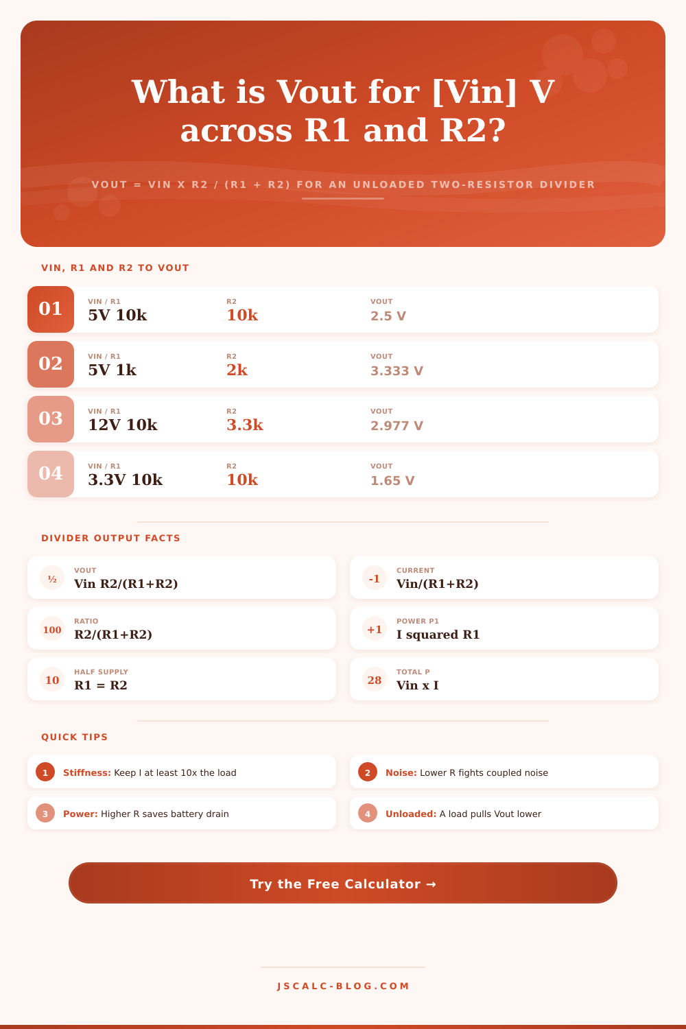
It’s pretty simple: Vout = Vin x R2 / (R1 + R2) So say you want to divide five volts with a couple ten-kilohm resistor. Twenty kilohms in all; that makes the ratio a half. You get two point five volts out. Swap lower resistor for another ten kilohms and now the ratio is two-thirds, bumping output up to around three point three three volts. For this, the voltage level depend only on the ratio. You could swap out a one-ohm resistor for a one-megohm one and it will still divide the input equally in half.
It’s the absolute values that determine how wasteful your device is, and that’s where it gets fun. The current through the resistors are simply Vin divided by the total resistance (since they’re in series). At 20 kilohms for five volts, that’s two hundred and fifty microamps. Each resistor dissipates power, which is the current squared times the resistance of each one. Total power drawn from your battery is therefore Vin times I. That tells you how much power your divider is burning. If you’re using this as part of a battery-powered sensor node, then every microamp counts; in a desktop unit powered off the mains, it hardly matters. Based off your power budget, you have to choose.
There are four primary outputs: division ratio; the divider current; total power used; and of course output voltage. The ratio card is a quick sanity check for your design. One third? That’s thirty-three percent. Half supply? That’s fifty percent. The breakdown panel lets you see exactly what numbers went into the calculation, so you know where it got its digits.
Want to use a particular tolerance? It’ll show you the realistic spread in Vout based on the tolerance. Real resistors aren’t perfect. A typical one-percent part will have a slight variation. The tool takes all the worst case corners and puts them together to show you the min/max output. That spread may be tens of millivolts for a two-point-five-volt tap. It is small stuff, sure. But when you’re feeding precision ADC input, it matters.
You get the unloaded output from this calculator (i.e., what the voltage is at the node with no load attached). As soon as you do attach some load, though, the load resistance goes in parallel with the bottom resistor of the divider and reduces the effective resistance at the output node. So you’re going to have less voltage than ideal. Your error gets smaller if your load has higher resistance relative to the divider. Engineers do make sure that the divider current is far higher than the load current; that’s why. However, if your load does draw significant current then you will need something else, like an op-amp buffer, or maybe even a different setup. But the unloaded value is always the right place to start when figuring out the possible voltage.
Those are the usual cases, and they’re covered by the built-in presets. There is one for a half-supply bias point, another for bringing a twelve-volt battery down into the ADC range, and another for scaling five volts down to three point three volts. These are great places to start, nudging values up and down to get as close as you want to your target without having to derive formula from scratch.
Pick a preset that’s relatively close to what you need. Compare the ratio to make sure the split’s appropriate. Look at current and power to make sure you don’t have a weak source that some load might mess around with, or waste a lot of energy. Twist ’em until Vout sits where you’d like it. The two knobs adjust just two things: the ratio moves the voltage; size of the resistors moves the current. And with those two dials, you can get pretty much any desired constant voltage drop dialed in.
A small thing, yes. But it matters.