Resistor Wattage Derating Calculator
Real resistors do not hold their full power rating once they run hot. Enter the rated watts, the actual dissipation, and the ambient temperature, pick a resistor type, and this tool applies the linear derating curve to give the derating factor, the effective power capacity, the nameplate rating you actually need, and the safety margin left at that temperature.
🎯Real Derating Presets
📝Resistor and Thermal Inputs
Nameplate wattage, valid up to the reference temperature.
Power the resistor really burns: I squared times R, or V times I.
Air temperature around the body, not the room thermostat.
Sets typical Tref and Tmax; switch to Custom to override.
Full rating holds up to here; commonly 70 C.
Zero-power point where the curve reaches 0; often 155 C.
Headroom you want left after derating; 20% is a good default.
Context only; it does not change the standard curve.
🔢Derating Formula Snapshot
📋Resistor Type Temperature Ratings
| Resistor Type | Tref (C) | Tmax (C) | Typical Curve | Notes |
|---|---|---|---|---|
| Carbon film | 70 | 155 | Linear to zero | Cheap, noisy, wide tolerance |
| Metal film | 70 | 155 | Linear to zero | Low noise, precise, common |
| Thick film (SMD) | 70 | 155 | Linear to zero | Chip size sets real limit |
| Thin film (SMD) | 70 | 155 | Linear to zero | Tight tolerance, low drift |
| Wirewound | 25 | 275 | Linear from 25 C | High power, runs very hot |
| Metal oxide | 70 | 235 | Linear to zero | Surge tolerant, hot rated |
| Precision foil | 70 | 145 | Linear to zero | Ultra stable, low power |
📊Derating Factor vs Ambient (Tref 70, Tmax 155)
| Ambient (C) | Derating Factor | 1 W Rated Gives | 0.25 W Gives | Zone |
|---|---|---|---|---|
| 25 | 100% | 1.000 W | 0.250 W | Full rating |
| 40 | 100% | 1.000 W | 0.250 W | Full rating |
| 55 | 100% | 1.000 W | 0.250 W | Full rating |
| 70 | 100% | 1.000 W | 0.250 W | Knee of curve |
| 85 | 82.4% | 0.824 W | 0.206 W | Derating |
| 100 | 64.7% | 0.647 W | 0.162 W | Derating |
| 125 | 35.3% | 0.353 W | 0.088 W | Steep loss |
| 155 | 0% | 0.000 W | 0.000 W | Do not use |
📏Actual to Required Rating Guide
| Actual Load | Ambient (C) | Factor | Required Rating | Pick a Part |
|---|---|---|---|---|
| 0.10 W | 25 | 1.000 | 0.10 W | 1/8 W is fine |
| 0.10 W | 100 | 0.647 | 0.155 W | Use 1/4 W |
| 0.25 W | 85 | 0.824 | 0.303 W | Use 1/2 W |
| 0.50 W | 100 | 0.647 | 0.773 W | Use 1 W |
| 1.00 W | 110 | 0.529 | 1.889 W | Use 2 W |
| 2.00 W | 125 | 0.353 | 5.667 W | Use wirewound |
| 5.00 W | 85 | 0.824 | 6.071 W | Use 10 W |
🗃Type and Ambient Comparison Grid
| Type | Rated W | Ambient | Tref/Tmax | Factor | Derated W | Verdict for 0.4 W Load |
|---|---|---|---|---|---|---|
| Metal film | 0.5 W | 25 C | 70/155 | 1.000 | 0.500 W | Safe, wide margin |
| Metal film | 0.5 W | 100 C | 70/155 | 0.647 | 0.324 W | Overloaded, size up |
| Carbon film | 1 W | 100 C | 70/155 | 0.647 | 0.647 W | OK, thin margin |
| Thick film | 0.25 W | 85 C | 70/155 | 0.824 | 0.206 W | Overloaded, size up |
| Thin film | 0.5 W | 70 C | 70/155 | 1.000 | 0.500 W | Safe at the knee |
| Wirewound | 1 W | 85 C | 25/275 | 0.760 | 0.760 W | Safe, good headroom |
| Wirewound | 1 W | 125 C | 25/275 | 0.600 | 0.600 W | Safe, watch mounting |
| Metal oxide | 0.5 W | 125 C | 70/235 | 0.667 | 0.333 W | Overloaded, size up |
⚙Formula Breakdown
💡Practical Derating Tips
A quarter-watt rated resistor doesn’t do a quarter watt in all environments. The quarter-watt rating is what manufacturer promises under 70 degrees Celsius (or whatever the temperature is). As ambient air temperature rises, safe power handling become lower. Without digging around in heavy datasheets, tool on this page reveals the underlying dependency on temperature so you know exactly how much power the resistor can still safely dissipate based off its rating, the ambient temperature, and how much it actualy dissipates. The result turns abstract limits into concrete safety margins.
And all resistors convert electrical energy into heat, which must be dissipated via their leads, the circuit board they’re on, or in surrounding air. Power rating of a part reflects how much it can dump heat in some assumed reference environment. When surrounding temperature increases, cooling difference driving heat out also decreases; if a resistor’s maximum allowable body temperature is exceeded, then it will lose less power before failing open-circuit. Resistance will begin to shift, its paint will start charring, solder joints will fatigue until finally the element give up. The practice of derating, then, is using a part at less than its nameplate rating, ensuring it survives true thermal conditions of your product design. It’s insurance for the heat you can’t see.
How to Keep Resistors Safe from Heat
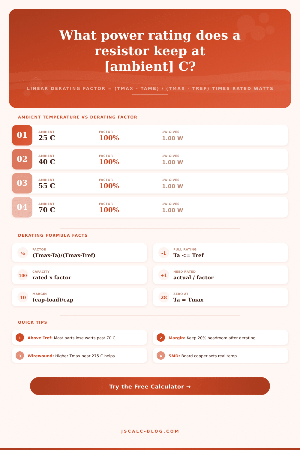
This calculator actualy uses a two part curve, which is what most film resistors follow. It starts with one hundred percent rating until the reference temperature (usually seventy degrees celsius) and a derating factor of one point zero. Past that, it drops off linear down to zero power at maximum temperature, which is usually one hundred fifty-five degrees celsius. The derating factor in that angled section is calculated by subtracting the ambient temperature from the maximum temperature, then dividing that result by difference between the maximum and reference temperatures. At or after the max, the derating factor are zero since the resistor can carry no more useful power at that temperature. This is exactly how you’d see this shown on the power derating graph printed on datasheet for your resistor.
Four result cards come back from the calculator, and they are all grounded in mathematical reality. First, look at the derating factor as a percentage at your ambient temperature. This lets you see quickly that a part operating at one hundred degrees Celsius may be worth only sixty-five percent of what is on the sticker. Second up: effective power capacity, or rated power times the factor. Third up: required nameplate rating for your actual load, or actual dissipation divided by the factor, to tell you how many watts you need to purchase so that when it gets hot, it will be safe. And fourth up: the safety margin, calculated as derated capacity less the load divided by the derated capacity, in percentage form. If the margin turn negative, the tool flags the resistor as overloaded.
Don’t worry, the type drop down isn’t just cosmetics, it sets entire curve’s temperature anchors. Parts generally fall into several category: thin film, thick film, metal film, carbon film. Generally, all those types has the same one hundred fifty-five-degree max and seventy-degree ref. Their curves will be different, but they are going to derate on the same slope. Metal oxide is somewhere in-between. Wirewound resistors tend to begin their derating at twenty-five degrees Celsius, but continue to carry full current up to about two hundred seventy-five degrees Celsius, meaning they has much greater usable headroom at high ambient temps.
The calculator allows you to select your technology or change the reference/maximums to a custom set if you’re matching a particular datasheet rather than guesswork. It also let you see how the same load performs across different resistor types. Let’s say you put a quarter-watt metal film resistor into an enclosure that gets up to eighty-five degrees Celsius, which dissipates point one five watts. Eighty-five is higher then the seventy-degree reference, so factor is zero point eight two four. Multiplying the resistance by this number give us a derated capacity of about zero point two zero six watts. Below that is your load. The safety margin is around twenty-seven percent. Everything is fine so far. Part’s not going to have a problem.
Now push the ambient temperature to one hundred ten degrees Celsius. The same resistor has only about zero point one three watts of capacity, which is below what you’re asking it to handle. The calculator warn there will be an overload. Sometimes all the difference between passing and failing is ten degrees of air.
A series of tables below the calculator convert the equation into fast-lookup forms. One table describes popular resistor types. It also show their normal operating curve and temperature range (max and ref). There’s another showing the derating factor at different ambient temps. Trace along line to see that a quarter-watt or one-watt part gets smaller as the ambient warms. The next table is a guide to turn the real load on a component at a certain temperature into the nameplate rating you should of spec for it. The final table lets you compare resistor technologies at a fixed load. It shows which one will stand up in a hot corner of your board. They’re here to let you cut out math if all you want is a quick sanity check.
The default set includes ten real world scenarios: a metal film part sitting on a chilly twenty-five degree bench, a chunky old thick film chip in a warm spot near a microcontroller, a wirewound resistor in an eighty-five-degree box, a carbon film part in a red-hot one hundred-degree engine bay, and a purposeful overload test so you can witness the behavior of warning. These presets fill the form instantly and recalculate as they go.
The guidance is always: leave yourself headroom. After derating, plan for at least a twenty-percent margin. When things like pulses, hot spots, or aging could eat into that margin, jump up to next higher wattage. For example, you could go from a quarter-watt to a half-watt. If used this way, the calculator assists your selection of components that are cool enough to stay accurate, and stay alive long enough to live through lifetime of product. Useless is a component that lasts a week but burns out in summertime. Plan for peak, not average.