Resistor Power Rating Calculator
Work out how many watts a resistor actually dissipates using P = I squared times R, P = V squared over R, or P = V times I, multiply by a safety factor, then pick the next standard 1/8 W to 10 W package and see how much headroom it leaves.
⚡Real Circuit Presets
🔌Resistor and Load Inputs
Choose your input; the matching fields appear below.
The resistor value, in ohms. Must be greater than 0.
Steady current in the resistor, in mA or A below.
Applies to the current field above.
Voltage drop over the resistor only, not the supply.
Enter dissipation in watts if you already know it.
Recommended rating = dissipation times this. 2x is typical.
A reminder only, hotter air means pick more margin.
🔢Power Formula Snapshot
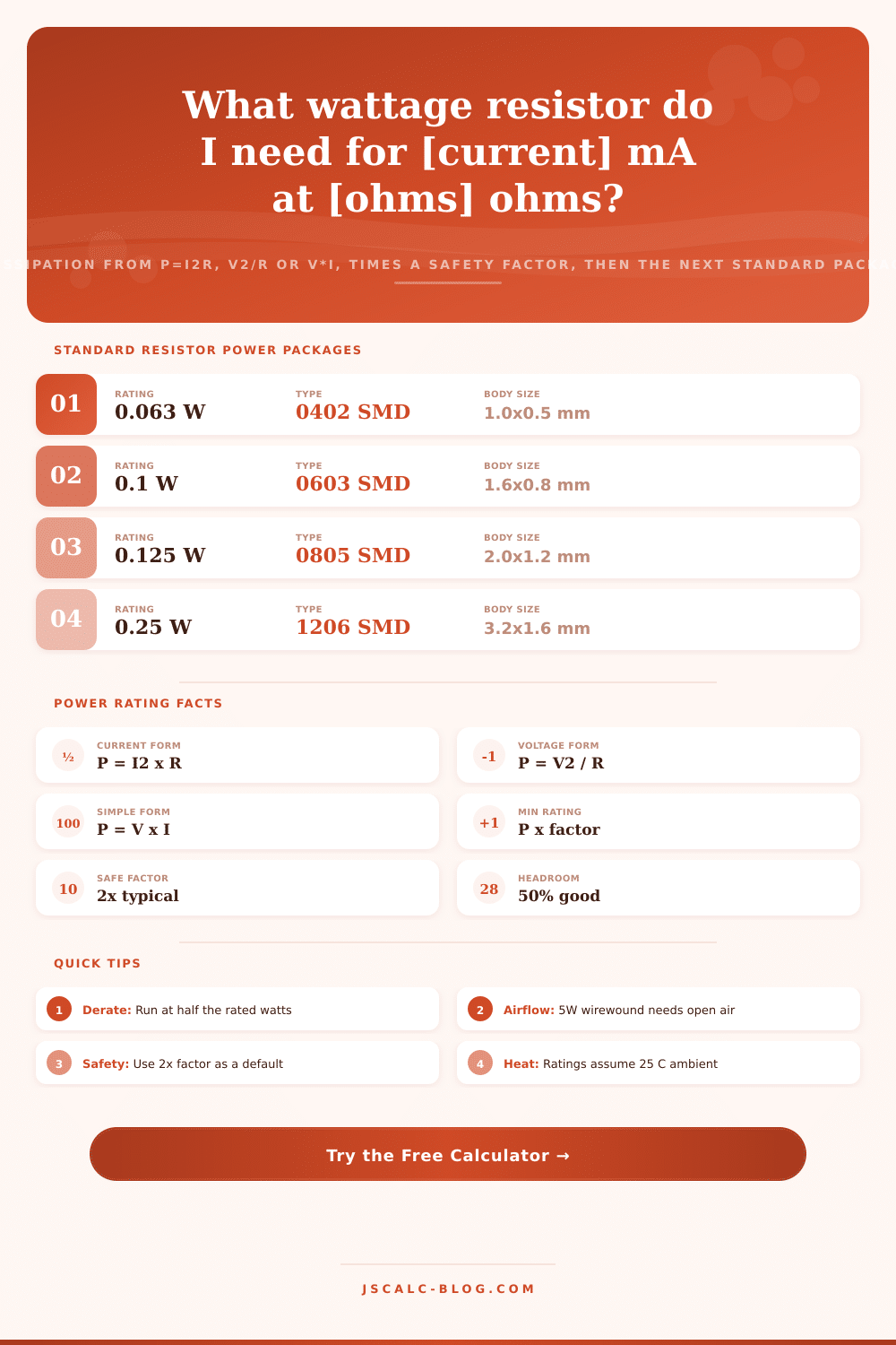
📋Standard Wattage Packages and Body Sizes
| Rating | Type | Typical Body Size | Common Use |
|---|---|---|---|
| 0.063 W (1/16) | 0402 SMD | 1.0 x 0.5 mm | Dense digital boards |
| 0.1 W (1/10) | 0603 SMD | 1.6 x 0.8 mm | Signal pull-ups |
| 0.125 W (1/8) | 0805 SMD | 2.0 x 1.2 mm | General SMD glue logic |
| 0.25 W (1/4) | 1206 SMD / Axial | 3.2 x 1.6 mm | Most through-hole work |
| 0.5 W (1/2) | Axial film | 9 x 3.5 mm | LED and bias networks |
| 1 W | Axial film | 11 x 5 mm | Small droppers |
| 2 W | Axial metal oxide | 15 x 5 mm | Snubbers, bleeders |
| 3 W | Wirewound | 17 x 6 mm | Higher power bias |
| 5 W | Ceramic wirewound | 22 x 8 mm | Brake, dummy loads |
| 10 W | Aluminum clad | 48 x 10 mm | Heatsink mounted loads |
🛡Safety Factor Guidance
| Safety Factor | Runs At | When To Use | Life Impact |
|---|---|---|---|
| 1.5x | 67% of rating | Cool air, short duty | Acceptable |
| 2x | 50% of rating | General default | Good, long life |
| 2.5x | 40% of rating | Warm enclosures | Very safe |
| 3x | 33% of rating | Continuous power parts | Runs cool |
| 4x | 25% of rating | Sealed or hot boxes | Excellent margin |
| 5x | 20% of rating | Safety critical loads | Barely warms |
📊Worked Scenario Comparison Grid
| Scenario | R (ohms) | I | V across R | Dissipation | Pick (2x) |
|---|---|---|---|---|---|
| LED limiter 5V | 220 | 15 mA | 3.3 V | 0.050 W | 0.125 W |
| 12V to 5V dropper | 70 | 100 mA | 7.0 V | 0.700 W | 2 W |
| Motor snubber | 47 | 150 mA | 7.1 V | 1.058 W | 3 W |
| Voltage divider | 10000 | 1.2 mA | 12 V | 0.014 W | 0.063 W |
| Gate pulldown | 10000 | 0.5 mA | 5.0 V | 0.003 W | 0.063 W |
| Current shunt | 0.1 | 3 A | 0.3 V | 0.900 W | 2 W |
| HV bleeder | 220000 | 1.36 mA | 300 V | 0.409 W | 1 W |
| Brake resistor | 10 | 2.4 A | 24 V | 57.60 W | Bank >10 W |
| Inrush limiter | 10 | 1 A | 10 V | 10.00 W | 10 W burst |
| I2C pull-up | 4700 | 0.7 mA | 3.3 V | 0.002 W | 0.063 W |
📏Current and Unit Conversions
| Unit | Equals | In Base Unit | Note |
|---|---|---|---|
| 1 A | 1000 mA | 1 A | Amp of current |
| 1 mA | 0.001 A | 0.001 A | Milliamp |
| 1 W | 1 V x 1 A | 1 W | Watt of heat |
| 1 W | 1000 mW | 1 W | Milliwatt scale |
| 1 kohm | 1000 ohms | 1000 ohms | Kilo-ohm |
| 1 Mohm | 1000000 ohms | 1000000 ohms | Mega-ohm |
⚙Formula Breakdown
💡Practical Power Rating Tips
That’s the smell you get when you’ve burnt something with your soldering iron, and it’s the smell of electrons dying as they fight your efforts to force them through their journey. You check the math on paper. Current is in spec. Resistor value matches schematic perfectly. But still, that part dies from thermal overload and not an electrical problem.
That’s a trick we engineers and hobbyists fall into all too easily. One number describes how well the resistor resists flow (the ohmic rating), the other describes how much heat this thing can absorbs (wattage). Sometimes getting the second number correct matters more then having gotten the first one just right.
Why Resistors Burn Out
Think of resistors as little heaters, burning up extra energy. Basic physics formulas shows us that heat is produced when current pass through a resistor. If you know the resistance and the current, square the current and multiply it by the resistance. If you have voltage drop instead then you square that number and divide it by resistance. Or just multiply both numbers if you have both.
That’s the kind of math the calculator does quickly for you, letting you concentrate on what the number means. It will take all the information about your circuit conditions and translate it into a heat load. How many watts are trying to leave through small body of the component? So you know how much raw dissipation there is.
Now what? Well, you now has to choose a safety factor for your design. If you operate something at its max rating, then you are running it really hot. Hot is bad; it ages all electronic materials, and it moves resistance value as well. Over time it cracks off the protective coating and breaks down solder joints.
The rule of thumb: Derate parts big-time! A solid starting point is to give yourself a 2x safety factor. This way you never use more than half of part’s rated ability. This gives you some margin for variations in ambient temperature and keeps the thing cool enough that you don’t care.
That recalculated value determines which physical package you pick. Resistors are available in standard wattages from small (0.125 W) to large (10 W). The calculator rounds up to next standard rating. You won’t have to search for hard-to-find products that aren’t actualy in stock. More importantly, it indicates how close you are to running out of safety margin.
If your calculation falls between two ratings, selecting the lower one may reduce your costs but run the risk of failing under continuous loading. Selecting the higher-rated one adds negligible cost for significant reliability gains. Now it’s not just about the number; it’s also about context.
That wattage rating given on a datasheet is for a perfect world. I.e., 25 C ambient air temperature and free convection cooling. If it’s sitting right next to some other hot-running component or stuffed into a small box, then that rating falls off by roughly half. When there’s restricted airflow, you may have to go up to 3x or more on your safety factor.
Those reference tables on that page will give you a feel for this. They illustrate why bigger resistors can handle more power than smaller ones. A tiny surface mount chip doesn’t get rid of heat as well as a larger axial leaded resistor, which uses its exposed leads as a heatsink.
Resistors are not simply there to meet an electrical requirement; they’re also there to respect their thermal limit. By thinking through the inputs, you make sure your design will survive far past the prototype stage. You choose a package that can handle the job, apply a reasonable margin of safety, and then all is well.
That humble resistor could actualy be the most expensive component in your circuit… More so even than the sensor and the microcontroller. After all, what good would of it do if everything burned down?