Smoothing Capacitor Size Calculator
Enter your load current and the maximum ripple voltage you can tolerate, then this tool solves C = I / (f x Vripple) for the minimum reservoir capacitor, rounds up to the next standard electrolytic value, reports the ripple you will actually get, and suggests a safe voltage rating for the part.
🎯Real Power Supply Presets
📝Power Supply Inputs
Steady DC current drawn by the load after the cap.
Peak-to-peak ripple you can accept on the rail.
Applies to the ripple field above.
Bridge charges the cap twice per AC cycle.
Mains frequency feeding the transformer.
Nominal rail voltage, used for the rating advice.
🔢Formula Snapshot
📋Load and Ripple Sizing Examples (Bridge, 50 Hz)
| Load Current | Target Ripple | C = I / (100 x Vr) | Standard Cap |
|---|---|---|---|
| 0.25 A | 1 V | 2500 uF | 3300 uF |
| 0.5 A | 0.5 V | 10000 uF | 10000 uF |
| 1 A | 1 V | 10000 uF | 10000 uF |
| 1 A | 0.5 V | 20000 uF | 22000 uF |
| 2 A | 1 V | 20000 uF | 22000 uF |
| 2 A | 0.5 V | 40000 uF | 47000 uF |
| 3 A | 1 V | 30000 uF | 33000 uF |
| 5 A | 2 V | 25000 uF | 33000 uF |
📊Ripple Frequency by Rectifier and Mains
| Rectifier | Pulses / Cycle | At 50 Hz | At 60 Hz | Cap vs Half-Wave |
|---|---|---|---|---|
| Half-wave | 1 | 50 Hz | 60 Hz | Baseline (largest) |
| Full-wave center-tap | 2 | 100 Hz | 120 Hz | Half the size |
| Full-wave bridge | 2 | 100 Hz | 120 Hz | Half the size |
| 3-phase half-wave | 3 | 150 Hz | 180 Hz | One third |
| 3-phase bridge | 6 | 300 Hz | 360 Hz | One sixth |
| Bridge at 400 Hz | 2 | 800 Hz | - | Tiny cap needed |
📏Standard Electrolytic Values (E6/E12)
| Value (uF) | Series | Common Rating | Typical Use |
|---|---|---|---|
| 470 | E6 | 35-63 V | Small logic rails |
| 1000 | E6 | 25-50 V | Low current supply |
| 2200 | E6 | 25-50 V | 1 A class rails |
| 3300 | E12 | 16-50 V | Medium reservoir |
| 4700 | E6 | 16-63 V | 2 A supplies |
| 10000 | E6 | 16-50 V | Audio and 2-3 A |
| 22000 | E6 | 16-63 V | Big amp rails |
| 47000 | E6 | 10-63 V | High current bank |
🗃Reservoir Capacitor Design Comparison Grid
| Supply | Load I | Target Vr | Ripple f | C Needed | Standard Cap |
|---|---|---|---|---|---|
| 5V logic | 1 A | 0.1 V | 100 Hz | 100000 uF | 100000 uF |
| 5V bench | 2 A | 0.5 V | 100 Hz | 40000 uF | 47000 uF |
| 12V bridge | 1 A | 1 V | 100 Hz | 10000 uF | 10000 uF |
| 15V preamp | 0.25 A | 0.5 V | 100 Hz | 5000 uF | 6800 uF |
| 24V LED | 2 A | 1 V | 100 Hz | 20000 uF | 22000 uF |
| 35V audio | 5 A | 2 V | 100 Hz | 25000 uF | 33000 uF |
| 48V rail | 3 A | 1 V | 100 Hz | 30000 uF | 33000 uF |
| 9V half-wave | 0.5 A | 1 V | 50 Hz | 10000 uF | 10000 uF |
| 250V tube | 0.15 A | 5 V | 100 Hz | 300 uF | 330 uF |
| 36V motor | 4 A | 2 V | 100 Hz | 20000 uF | 22000 uF |
⚙Formula Breakdown
💡Capacitor Selection Tips
An unregulated DC power supply performs according to its reservoir capacitor. Choose a bad one (too small) and you have ripple and sagging voltage rails. Ripple stresses other components, confuses digital logic, and hums through your audio gear. If you pick an oversized capacitor to avoid dealing with ripple values, you’ll end up wasting money and board space. A big capacitor cause high inrush current at power-on time.
The solution is this page’s smoothing capacitor size calculator. Tell it your load current draw and your allowable ripple, and it’ll give you the minimum capacitance, the nearest available real-world part number, the resultant ripple, and a reasonable voltage rating.
How to Choose the Right Capacitor Size
The mains voltage are stepped down by a transformer, then rectified so it only contains positive half cycles. Its voltage is now a row of humps instead of a flat line. The smoothing capacitor starts charging for every hump until it reaches its maximum value, the height of the hump. Then as the rectifier output fall again (the gaps), it provides current to the load using the charge it has collected. So it rises and droops a little with each pulse, springing back again as the next one arrives. That droop is what we call the ripple voltage, a sort of saw tooth pattern.
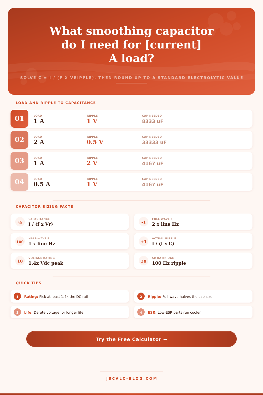
The larger the capacitor, the greater amount of charge it can hold, and the smaller the droop will be. So the design task here are determining how much capacitance will result in an acceptably small droop. The formula for computing it’s C = I / (f x Vripple) I stands for the load current. The Vripple stands for the max ripple voltage you want in volts. The variable f is the ripple frequency expressed in hertz: the number of times per second that the capacitor tops itself back up.
This calculator solves for size direct. You put in a target ripple value and it tells you what size capacitor you need. It doesn’t start with a known capacitor and then tell you what the ripple would be. That makes a big difference because typicaly when you’re designing something you don’t know the capacitor until after the fact. What you do have are your load values and your ripple budget. You need the component that meets those specs.
The ripple frequency f depend on which kind of rectifier you choose. For a half wave rectifier it’s just once per mains cycle (so 50 times a second if you’re using 50Hz mains). For a full wave rectifier, whether bridge or otherwise (it’s twice that: 100 times a second). Moving from a half-wave rectifier to a full-wave rectifier halves the capacitance requirement for the same ripple. That’s one of the largest savings a supply designer can make. This is also the reason bridge rectifiers are commonplace. The calculator allows you to select mains frequency and rectifier type and see the required value change.
So how do we land on a value you can buy? The formula rarely lands on one. There are preferred series of electrolytic capacitors. For example, there are the E6 and E12 series. These have values like 470, 680, 1000, 1500, 2200, 3300, 4700, 6800, 10000 microfarads and so on.
Microfarad. Always round up to the next standard value (at or above) the calculated minimum. Never round down! That’s just good engineering. This tool automaticly snaps your result to the next larger stock value. Then it feeds that real capacitance back into the ripple formula and reports the ripple you will really measure. Because you rounded up the capacitance, this measured ripple is comfortabley below your target.
That’s only half the spec. Because it smooths out the rectified waveform, the cap has to charge to its peak. That’s about 1.414 times the nominal DC rail before losses. In other words, an actual 12 volt rail is closer to 17 volts on peak. If you fit a 16 volt capacitor in that position, you’d have barely any margin. As a rough guide, I always use a minimum rating of 1.4 x the real peak. Snap up from there to a round rating like 25, 35 or 50 volts.
The calculator guesses the peak based off the DC output voltage you enter. It suggests a minimum rating which assumes headroom. This provides safety against voltage creep over time with a lightly loaded supply. It also protects against occasional surges.
The summary cards shows the design results in four lines. First is the minimum capacitance direct from the equation. Second is the stock component to get. Third is the actual ripple with the chosen part fitted. Fourth is the recommended voltage rating. In a break-down panel, all the numbers used as substitutions are listed out so they can be dropped into a design note and checked for the arithmetic.
Presets cover a range of typical supplies. These range from a 5 volt 2 amp bench supply with half a volt of ripple, through a 12 volt 1 amp bridge based on 50 Hz mains to a 48 volt 3 amp industrial rail and even a 250 volt tube amplifier B+ line. Start roughly where your project is, then fine-tune from there.
For real supplies, two caveats apply. First, the easy formula neglects capacitor ESR and a varying load current. Always round up and consider the result only a good starting point. Allow some extra room for component variations and transformer sag. 2) A massive reservoir capacitor will draw a hell of an inrush spike when it’s charging up from zero. That can blow fuses or weld relay contacts. Instead of just adding capacitance to decrease ripple, high-current designs usually includes some kind of inrush limiter or soft-start.
So how do you size a smoothing capacitor? It’s quick and it’s repeatable. You measure the load current, estimate what ripple you can tolerate, select your rectifier, and then choose mains frequency and peak voltage. You use the formula C = I / (f x Vripple) and there’s the answer. That whole calculation chain is executed in a flash with this calculator. It makes sense of a job previously consisting of a favourite value chart, a datasheet, and a couple of minutes on the calculator.
Give it one click and it returns a reliable voltage and capacitance rating within seconds for whatever you’re trying to build from a hi-fi amplifier rail through to an industrial DC bus or hobby bench supply. And it restores the humble reservoir capacitor to its purpose as a simple buffer between the AC chaos outside and the circuit stability inside.