Capacitor Ripple Voltage Calculator
Analyze the ripple a known filter capacitor actually produces in a linear power supply. Enter the load current, the capacitance you already have, and the rectifier type, and this tool reports peak-to-peak ripple Vpp, the RMS ripple, the ESR voltage contribution, and the ripple as a percentage of your DC output using Vpp = I / (f_ripple x C).
⚡Real Power Supply Presets
🔌Power Supply Inputs
Steady DC current the circuit pulls from the reservoir capacitor.
The reservoir or smoothing capacitor you already have installed.
1 mF = 1000 uF and 1 F = 1000000 uF.
Bridge and full-wave rectifiers charge the cap twice per cycle.
Mains input frequency before rectification.
Equivalent series resistance adds an I x ESR spike. Set 0 to ignore.
Average rail voltage, used only to express ripple as a percentage.
Controls rounding on every result card.
🔢Formula Snapshot
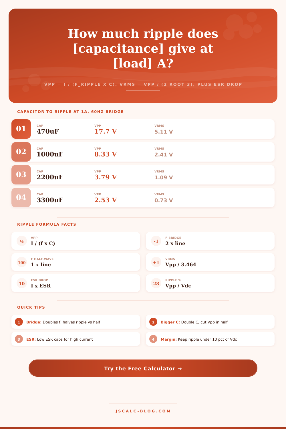
📋Capacitance to Ripple (1A, 60Hz Bridge)
| Capacitance | Ripple Freq | Vpp | Vrms |
|---|---|---|---|
| 470 uF | 120 Hz | 17.73 V | 5.12 V |
| 1000 uF | 120 Hz | 8.33 V | 2.41 V |
| 2200 uF | 120 Hz | 3.79 V | 1.09 V |
| 3300 uF | 120 Hz | 2.53 V | 0.73 V |
| 4700 uF | 120 Hz | 1.77 V | 0.51 V |
| 6800 uF | 120 Hz | 1.23 V | 0.35 V |
| 10000 uF | 120 Hz | 0.83 V | 0.24 V |
| 22000 uF | 120 Hz | 0.38 V | 0.11 V |
📊Rectifier and Line Frequency Effect
| Rectifier | Line Freq | Ripple Freq | Charge Pulses | Relative Ripple |
|---|---|---|---|---|
| Half-wave | 50 Hz | 50 Hz | 1 per cycle | Highest |
| Half-wave | 60 Hz | 60 Hz | 1 per cycle | Very high |
| Full-wave CT | 50 Hz | 100 Hz | 2 per cycle | Half of HW |
| Full-wave CT | 60 Hz | 120 Hz | 2 per cycle | Lowest AC |
| Bridge | 50 Hz | 100 Hz | 2 per cycle | Half of HW |
| Bridge | 60 Hz | 120 Hz | 2 per cycle | Lowest AC |
| Bridge | 400 Hz | 800 Hz | 2 per cycle | Very low |
📏Typical Electrolytic ESR Values
| Capacitor | Voltage | Typical ESR | Ripple Rating |
|---|---|---|---|
| 470 uF | 35 V | 0.20 ohm | 0.8 A |
| 1000 uF | 25 V | 0.10 ohm | 1.4 A |
| 2200 uF | 25 V | 0.06 ohm | 2.0 A |
| 4700 uF | 35 V | 0.03 ohm | 3.1 A |
| 10000 uF | 50 V | 0.02 ohm | 5.6 A |
| 22000 uF | 63 V | 0.015 ohm | 8.2 A |
🗃Ripple Comparison Grid (60Hz Bridge)
| Load I | Capacitance | Ripple Freq | Vpp | Vrms | Ripple % at 12V |
|---|---|---|---|---|---|
| 0.1 A | 1000 uF | 120 Hz | 0.83 V | 0.24 V | 6.9 % |
| 0.5 A | 2200 uF | 120 Hz | 1.89 V | 0.55 V | 15.8 % |
| 1 A | 2200 uF | 120 Hz | 3.79 V | 1.09 V | 31.6 % |
| 1 A | 4700 uF | 120 Hz | 1.77 V | 0.51 V | 14.8 % |
| 2 A | 4700 uF | 120 Hz | 3.55 V | 1.02 V | 29.5 % |
| 2 A | 10000 uF | 120 Hz | 1.67 V | 0.48 V | 13.9 % |
| 3 A | 10000 uF | 120 Hz | 2.50 V | 0.72 V | 20.8 % |
| 5 A | 22000 uF | 120 Hz | 1.89 V | 0.55 V | 15.8 % |
| 5 A | 33000 uF | 120 Hz | 1.26 V | 0.36 V | 10.5 % |
⚙Formula Breakdown
💡Ripple Reduction Tips
The transformer is humming on the bench because you built a power supply. You soldered in a big old electrolytic capacitor from an old computer power supply (because it looked like it could handle it). But when you check the voltage with a multimeter, it’s not steady. It varies. That’s ripple voltage; alternating current left over in your direct current output.
A reservoir capacitor don’t charge smoothly. Instead it charges during pulses coming from the rectifier, then discharges as electricity flows out of it as the load consume energy. Before you solder anything, the calculator on this page will predict those peaks so that you don’t have any noise problems later when your circuit won’t work right.
How to Calculate Ripple Voltage
It’s very simple math at its core. The load current divided by the product of ripple frequency and capacitance equals the peak-to-peak ripple voltage. This is the load current. That’s a straightforward capacitor equation for discharge under a constant current through a given capacitance over time. Frequency is the inverse of time between pulses.
Doubling the capacitance cuts the ripple in half. Doubling the load current double the ripple. It is a direct trade-off where your input numbers matters most. Frequency is also important because type of rectifier makes all the difference. A full wave (or bridge) rectifier takes both halves of an AC cycle, whereas a half wave rectifier only let through one half.
So instead of charging once per mains cycle (which is sixty hertz in North America, fifty in Europe), the capacitor are charged twice as fast at one hundred hertz (full-wave) or one-hundred-twenty hertz (bridge). Since ripple is proportional to frequency, doubling the frequency cuts ripple voltage in half instantaneous with no component change whatsoever. No wonder you see bridge rectifiers used in designs.
Frequency multiplies automatically in tool’s calculations, you don’t need to remember those relations. Equivalent Series Resistance (ESR) is a factor ignored by most novice capacitor user. Capacitors are not ideal components; they’re real. There’s an internal resistance that behaves as a little resistor in series with the capacitor plates. The rectifier then fires, and dumps a sharp pulse of charging current into the cap.
Some of that current flow through the internal ESR, creating an instantaneous voltage spike atop discharge curve. This may only involve a few negligible millivolts if the current is low. However, at several amps that spike can adds volts to your ripple figure. Designing a bench supply or powering a motor driver while ignoring ESR will result in optimistic results. Looks great on paper but overheats in reality.
Next you have ripple. How much ripple can you tolerate? A three hundred volt tube amp with two volts of ripple running on its plate rail sounds fine. Running a sensitive five volt logic circuit powered based off that same source that trips out at four point eight volts is a problem. Ripple expressed as a percentage of your DC output voltage lets you compare things.
For example, a general rule for linear regulators is to not exceed ten percent peak-to-peak ripple of your rail voltage. That leaves the regulator some breathing room to clean up the voltage before it get too hot and shuts down. If you are feeding raw power into an analog audio stage, you don’t want that number that high or you’ll hear hum. These relationships is shown in the reference tables on this page for common situations.
Note, for instance, that at a given load a four hundred seventy microfarad capacitor will behave different than ten thousand microfarads. Because of cost and size, there are limits to how much more capacitance makes sense, there is diminishing returns. Sometimes it’s simpler just to use two lower value caps in parallel instead, which halves the ESR.
A clean power rail is all about trade offs: component size vs. Ripple tolerance; frequency advantages vs. Circuit complexity; cost vs. Performance. Enter your parameters into the calculator, and it do the math for you. It translates theory into real voltage numbers. Plug in what you know, and it will tell you what happens. And then you’ll figure out whether that fluctuating voltage is quiet enough for your project or not.
Or perhaps you’d prefer a differnt rectifier topology? Or a bigger capacitor?