PWM Frequency Calculator
Compute PWM frequency from a timer clock, prescaler and TOP register with f = f_clock / (prescaler x (TOP + 1)), get the PWM period and the duty resolution in bits and steps, or switch to solve mode to find the TOP value that hits a target frequency on an 8, 10, 12 or 16-bit timer.
🔌Choose a Mode
🎯Real MCU Timer Presets
📝Timer Inputs
Clock feeding the timer before the prescaler.
Applies to the clock frequency field.
Counter ticks at clock divided by this value.
Sets the maximum allowed TOP value.
Counter reloads at TOP; period is TOP + 1 counts.
Desired output frequency to solve TOP for.
Applies to the target frequency field.
Controls rounding on every result card.
🔢Formula Snapshot
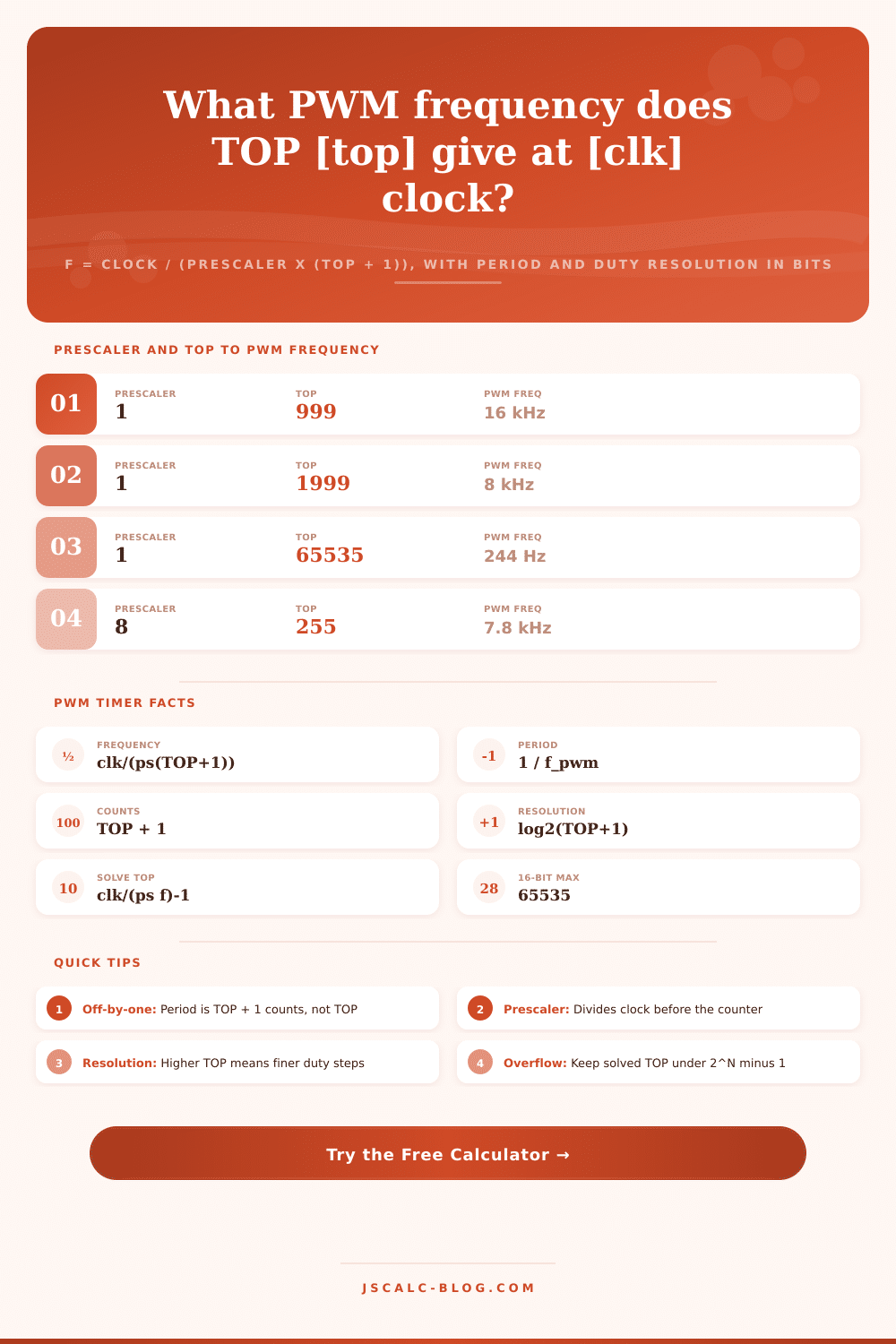
📋Prescaler and TOP to Frequency (16 MHz clock)
| Prescaler | TOP | Counts (TOP+1) | PWM Frequency | Reads As |
|---|---|---|---|---|
| 1 | 999 | 1000 | 16.00 kHz | Fast motor PWM |
| 1 | 1999 | 2000 | 8.000 kHz | Audible whine gone |
| 1 | 799 | 800 | 20.00 kHz | Ultrasonic drive |
| 1 | 65535 | 65536 | 244.1 Hz | Full 16-bit LED |
| 8 | 255 | 256 | 7.813 kHz | 8-bit fast PWM |
| 8 | 4999 | 5000 | 400.0 Hz | Coarse dimming |
| 64 | 999 | 1000 | 250.0 Hz | Slow LED fade |
| 256 | 1249 | 1250 | 50.00 Hz | RC servo pulse |
📊Timer Bit Width and Duty Resolution
| Resolution | TOP Max | Counts Max | Duty Steps at Full TOP | Duty Bits |
|---|---|---|---|---|
| 8-bit | 255 | 256 | 256 steps | 8.00 bits |
| 10-bit | 1023 | 1024 | 1024 steps | 10.00 bits |
| 12-bit | 4095 | 4096 | 4096 steps | 12.00 bits |
| 14-bit | 16383 | 16384 | 16384 steps | 14.00 bits |
| 16-bit | 65535 | 65536 | 65536 steps | 16.00 bits |
| 32-bit | 4294967295 | 4.29 billion | Very fine | 32.00 bits |
🧩Common MCU PWM Configurations
| Platform | Clock | Prescaler | TOP | Resulting Frequency |
|---|---|---|---|---|
| Arduino Uno pin 5/6 | 16 MHz | 64 | 255 | 976.6 Hz |
| Arduino Uno pin 9/10 | 16 MHz | 1 | 255 | 62.50 kHz |
| STM32 general timer | 72 MHz | 72 | 999 | 1.000 kHz |
| STM32 motor PWM | 72 MHz | 1 | 3599 | 20.00 kHz |
| ESP32 LEDC channel | 80 MHz | 1 | 16383 | 4.883 kHz |
| ATmega servo Timer1 | 16 MHz | 8 | 39999 | 50.00 Hz |
| RP2040 PWM slice | 125 MHz | 125 | 999 | 1.000 kHz |
📏PWM Period and Frequency Conversions
| Frequency | Period | Period in ms | Typical Use |
|---|---|---|---|
| 50 Hz | 0.02 s | 20 ms | RC servo, mains AC |
| 490 Hz | 0.00204 s | 2.04 ms | Arduino default PWM |
| 1 kHz | 0.001 s | 1 ms | General LED dimming |
| 20 kHz | 0.00005 s | 0.05 ms | Silent motor drive |
| 25 kHz | 0.00004 s | 0.04 ms | PC fan control |
| 100 kHz | 0.00001 s | 0.01 ms | Switching supply |
🗃Frequency, Prescaler and TOP Comparison Grid
| Clock | Prescaler | TOP | PWM Freq | Period | Duty Bits |
|---|---|---|---|---|---|
| 16 MHz | 1 | 999 | 16.00 kHz | 62.50 us | 9.97 bits |
| 16 MHz | 8 | 39999 | 50.00 Hz | 20.00 ms | 15.29 bits |
| 16 MHz | 64 | 255 | 976.6 Hz | 1.024 ms | 8.00 bits |
| 72 MHz | 1 | 3599 | 20.00 kHz | 50.00 us | 11.81 bits |
| 72 MHz | 72 | 999 | 1.000 kHz | 1.000 ms | 9.97 bits |
| 80 MHz | 1 | 15999 | 5.000 kHz | 200.0 us | 13.97 bits |
| 80 MHz | 1 | 799 | 100.0 kHz | 10.00 us | 9.64 bits |
| 125 MHz | 125 | 999 | 1.000 kHz | 1.000 ms | 9.97 bits |
| 48 MHz | 1 | 1919 | 25.00 kHz | 40.00 us | 10.91 bits |
| 168 MHz | 1 | 65535 | 2.563 kHz | 390.1 us | 16.00 bits |
⚙Formula Breakdown
💡PWM Tuning Tips
If you’ve worked with an Arduino hooked up to a motor, then you know that the resulting high-pitched whine sounds like this: You control how long it’s on (the duty cycle). However, it is hard to hear anything else because PWM frequency is in the range humans can hear. To fix this, we don’t need to guess at what code will work; instead, we can learn about the timer peripheral arithmetic.
All microcontrollers produces PWM by counting up from zero until they reaches a maximum number and start over. How fast does this happen? The answer is based off three variables: This is the clock source. The prescaler It’s a simple formula, but in practice, most folks does it wrong.
How to Fix Motor Noise with Math
It turns out that they forgot that counter values begins at zero. They also forgot about that pesky one added to the top value. The result is one thousand ticks for a top value of nine hundred and ninety-nine. That one tick throws off frequency calculation unless you remember to add it back in.
When you’re trying to hit a precise target such as twenty kilohertz for a silent motor drive or fifty hertz for an RC servo, this get compounded. A prescaler acts as a dividing chip between the counter and the system clock. It chops up the input rate at which it counts. If you have a big enough counter register to count all the way to 0 before overflowing, then a large prescaler will bring those rates down even more. But now each “tick” on the counter is a less precise measure of time. Your step-duties gets chunky. You can’t finely control your speed or brightness anymore.
A smaller prescaler gives higher resolution but requires a very high number in the top counter register to achieve same slowdown. That’s where a calculator comes into play. You plug in how fast your chip runs and how slow you want it to tick. Instead of fiddling with algebra when you’re debugging, it give you the right top value without any work.
To make your STM32 run at twenty kilohertz from its seventy-two megahertz crystal, you’d set the top register to three thousand five hundred and ninety-nine (which is exactly what math says). And if it’s larger than your timer can handle, it’ll let you know that, too. Is it eight bits at most? An eight-bit timer maxes out at two hundred fifty-five. Anything higher than that, and you’ll get overflows or something goofy happening until you change the prescaler or switch chips.
Sometimes more than just frequency is important; resolution is also critical in many situations. An eight bit resolution on an LED dimmer can show banding that’s visually objectionable when you’re looking for gradient subtlety. Sixty-five thousand different steps is smoother, now we’re using a sixteen-bit timer. At high frequencies, however, it takes some attention to make sure you keep the upper register dense enough and still have that full range of steps. For all combinations, the tool displays actual duty resolution (in bits) achieved. Does the increased prescaler makes the reduced resolution worthwhile?
Preset is typically where real world tuning begins. A standard servo timing preset or an Arduino PWM is familiar to most engineers. They are good starting points as they compensate for internal clock dividers and crystal oscillators that is used in commonly available boards. From there one tweaks one variable and sees what happens. Often lowering the frequency reduce noise but raises the top value. This impacts the number of discrete level it can be controlled by.
All of this comes back to PWM configuration: it’s one of those balance-a-few-competing-constraints problems. You want a high enough frequency that it won’t be heard or visible as flickering light. You also want a frequency or resolution high or low enough that the motor still move smoothly. And then there are the register values… You’d like something that sits well inside the operating range for your hardware.
When you make the three quantities (clock, prescaler, top value) explicit, you no longer guess at their values; you design them. Once the numbers come out right, the room ceases its whining. Now all you hear is the quiet hum of efficient power delivery. You should of used a calculator sooner to avoid the moddern issues. Actualy, it would of helped with the luxurios setup.