PWM Duty Cycle Calculator
Find PWM duty cycle three ways: from on-time and period using D = T_on / T_period times 100, from timer registers with D = CCR / (TOP + 1), or from a target average voltage with D = V_avg / V_supply. Get the duty percent, on-time, off-time, and average output voltage for motors, LEDs, servos, and heaters.
🔌Choose a Mode
🎯Real PWM Setup Presets
📝PWM Inputs
Switching rate; period T = 1 / frequency.
Applies to the frequency field above.
High time of the pulse within one period.
Applies to the on-time field above.
Timer compare register that sets on-time counts.
Period equals TOP + 1 counts; D = CCR / (TOP + 1).
Desired filtered output; D = V_avg / V_supply.
High-level rail driving the load.
Controls rounding on every result card.
🔢Formula Snapshot
📋On-Time and Period to Duty Cycle
| On-Time T_on | Period T | Duty D = Ton / T | Reads As |
|---|---|---|---|
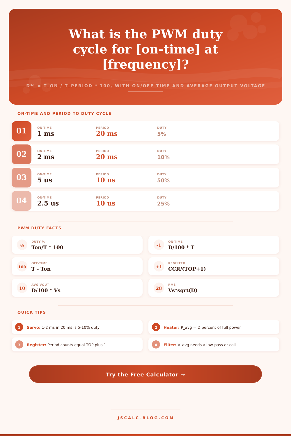
| 1 ms | 20 ms | 5% | Servo minimum |
| 1.5 ms | 20 ms | 7.5% | Servo center |
| 2 ms | 20 ms | 10% | Servo maximum |
| 2.5 us | 10 us | 25% | Quarter on |
| 5 us | 10 us | 50% | Square, half on |
| 7.5 us | 10 us | 75% | Three-quarter on |
| 9 us | 10 us | 90% | Nearly always on |
| 0 ms | any | 0% | Fully off |
📊Register CCR / TOP to Duty Cycle
| CCR (compare) | TOP (ARR) | Period Counts | Duty = CCR / (TOP+1) | Resolution |
|---|---|---|---|---|
| 128 | 255 | 256 | 50.0% | 8-bit |
| 64 | 255 | 256 | 25.0% | 8-bit |
| 191 | 255 | 256 | 74.6% | 8-bit Arduino |
| 512 | 1023 | 1024 | 50.0% | 10-bit |
| 700 | 999 | 1000 | 70.0% | STM32 1000 |
| 2048 | 4095 | 4096 | 50.0% | 12-bit |
| 3276 | 4095 | 4096 | 80.0% | 12-bit |
⚡Average Voltage and Power by Duty
| Duty D | V_avg at 5 V | V_avg at 12 V | RMS at 5 V (resistive) | Power Fraction |
|---|---|---|---|---|
| 10% | 0.50 V | 1.20 V | 1.58 V | 10% |
| 25% | 1.25 V | 3.00 V | 2.50 V | 25% |
| 40% | 2.00 V | 4.80 V | 3.16 V | 40% |
| 50% | 2.50 V | 6.00 V | 3.54 V | 50% |
| 66% | 3.30 V | 7.92 V | 4.06 V | 66% |
| 75% | 3.75 V | 9.00 V | 4.33 V | 75% |
| 100% | 5.00 V | 12.0 V | 5.00 V | 100% |
📏Frequency, Period, and Time Units
| Frequency | Period T = 1 / f | In Seconds | Note |
|---|---|---|---|
| 50 Hz | 20 ms | 0.02 s | Servo frame |
| 490 Hz | 2.04 ms | 0.00204 s | Arduino default |
| 1 kHz | 1 ms | 0.001 s | General LED |
| 20 kHz | 50 us | 0.00005 s | Quiet motor drive |
| 100 kHz | 10 us | 0.00001 s | Buck converter |
| 1 us | 1 MHz | 0.000001 s | 1 us equals 1 MHz |
🗃Duty Cycle Comparison Grid
| Application | Frequency | Period T | On-Time | Off-Time | Duty D | V_avg (5 V) |
|---|---|---|---|---|---|---|
| Servo min | 50 Hz | 20 ms | 1.0 ms | 19.0 ms | 5% | 0.25 V |
| Servo center | 50 Hz | 20 ms | 1.5 ms | 18.5 ms | 7.5% | 0.38 V |
| Servo max | 50 Hz | 20 ms | 2.0 ms | 18.0 ms | 10% | 0.50 V |
| LED dim | 1 kHz | 1 ms | 0.25 ms | 0.75 ms | 25% | 1.25 V |
| LED half | 1 kHz | 1 ms | 0.5 ms | 0.5 ms | 50% | 2.50 V |
| Motor drive | 20 kHz | 50 us | 37.5 us | 12.5 us | 75% | 3.75 V |
| Heater | 1 kHz | 1 ms | 0.4 ms | 0.6 ms | 40% | 2.00 V |
| Buck 3.3 V | 100 kHz | 10 us | 6.6 us | 3.4 us | 66% | 3.30 V |
| STM32 CCR700 | 1 kHz | 1 ms | 0.7 ms | 0.3 ms | 70% | 3.50 V |
| Full on | any | T | T | 0 | 100% | 5.00 V |
⚙Formula Breakdown
💡Practical PWM Tips
The way pulse width modulation functions is to turn a voltage on and off rapidy. To your eye… Or to some sort of mechanical load, it appear as an average effect rather than the choppy reality. The duty cycle is a single number that describes what’s happening. It represent how long the signal remains in high state during any given cycle. Simply divide the on-time by the overall period to get it.
As a developer, when you’re debugging your code it’s annoying to have to do this math by hand. That’s why the calculator above do the arithmetic for you. Now you can concentrate on whether your timing is even reasonable for your hardware.
How to Calculate Pulse Width Modulation Duty Cycle
Duty cycle is simply a ratio in terms of a percentage. A one-kilohertz switch take place every millisecond. So if the voltage is held high for half that period, your duty cycle is fifty percent. This creates a square wave where there’s an equal amount of on and off time. Hold it high for a quarter of a millisecond and your duty decreases to twenty-five percent.
But you can see here that the period are the reciprocal of frequency. So while you’ve increased the speed of the switching, the window during which that percentage applies has changed. This is why people often mistakenly think that a faster switch means brighter or somehow increases power. It doesn’t.
A microcontroller doesn’t typically allow you to specify a period directly in milliseconds or seconds. Rather, it’s got integer counters that increment until reaching some limit. That’s why there’s this business with registers and modes. In register mode, you load a top value (TOP), which specifies the number of ticks that comprise one complete period, then you specify a compare value (usually referred to as CCR) that indicates when output should flip high or low. Your duty cycle is equal to the compare value divided by the top value… But notice it has to be the top value +1 because the counter count from 0 on up! Omitting that extra count will throw off your calculation slightly. When you’re attempting to dead-center a servo, it becomes not so small.
Finally, work backwards from the voltage. You might want some other analog voltage, say, three point three volts for compatibility with some logic system… And all you’ve got is five-volt rail. If the load averages in the pulses it’s not hard to pretend you’re generating that kind of DC voltage using PWM. Feed it through a motor winding, or an RC filter to smooth out the spikes, and the resulting average is just supply voltage times the duty cycle. Sixty-six percent duty gets you down to three point three from five. At whatever switching rate you choose, the tool figures it out immediately, displaying the precise pulse width needed to get there.
It makes clear a subtle trick about power dissipation, too. Root mean square voltage is not the same as average voltage. The RMS value plays into how much energy are delivered by a waveform to a resistive load such as a heater element or a coil. In other words, for heating, it’s all about the square root of the duty cycle. Is it a fifty percent duty cycle? The RMS voltage will be about seven tenths times the supply voltage, whereas the average voltage would be half the supply. That means the heat produced do not increase at the same rate than the average voltage measured on the load. Knowing this difference lets you avoid over-estimating the thermal stress in your design. It is a subtle point, but it matters when things get hot.
Servo motors are special: they have an extremely narrow duty range. They will accept a pulse anywhere from one to two milliseconds in a twenty-millisecond frame. In percentage terms, that’s just five to ten percent! That’s the whole control window located at the very low end of the percentage scale. Attempting to control them with a generic zero-to-one-hundred slider wastes most of your resolution. Clicking on the preset buttons in the calculator will help you imagine what small differences in microseconds look like in terms of position change. It makes you realize that for servos, time is more intuitive when it’s absolute rather than relative duty.
That’s just a practical compromise between frequency choices. Typically, you’ll see motors running around twenty kilohertz. That frequency is high enough to move audible sound out of range for our ears and also make for smaller filters. But it means more electromagnetic interference and higher transistor losses due to faster switching. On the other hand, lower frequencies will buzz motors or flicker lights, but are easier to handle. To choose a good middle ground for your use, use the reference tables from that page, which match popular frequencies with their corresponding period. You want fast enough to be smooth, but slow enough to stay cool.
At its heart, PWM’s all about trading continuous control for digital precision. You’re chopping up the voltage finely, but you aren’t changing it smoothly. To get the chop right, you need to know your load type, your compare registers, and your period. Knowing that stuff can save you hours of trial and error when you’re trying to size a capacitor on a power supply or debug a microcontroller timer. It’s just a matter of numbers and the math’s easy if you lay it out, but it’s difficult to keep straight in your head as you’re wiring up a prototype. Let the tool do the dividing so you can concentrate on the circuit.