555 Timer Frequency Calculator
Compute the output frequency, period, duty cycle, and the individual high and low times of a classic 555 timer in astable oscillator mode from R1, R2 and C, or switch to monostable one-shot mode to size a single output pulse with t = 1.1 x R x C.
⏱Choose a Timer Mode
🎯Real 555 Circuit Presets
🔧Timing Component Inputs
Between Vcc and pin 7; carries charge and discharge current.
Between pin 7 and pins 2/6; sets the discharge (low) time.
Single resistor from Vcc to the timing capacitor for the one-shot.
Charges through R1 + R2 and discharges through R2.
Timing is Vcc independent; used only for context notes.
Controls rounding on every result card.
🔢Formula Snapshot
📋Common R and C to Frequency (Astable)
| R1 | R2 | Capacitor C | Frequency | Duty Cycle |
|---|---|---|---|---|
| 1 kohm | 10 kohm | 10 nF | 6.86 kHz | 52.4% |
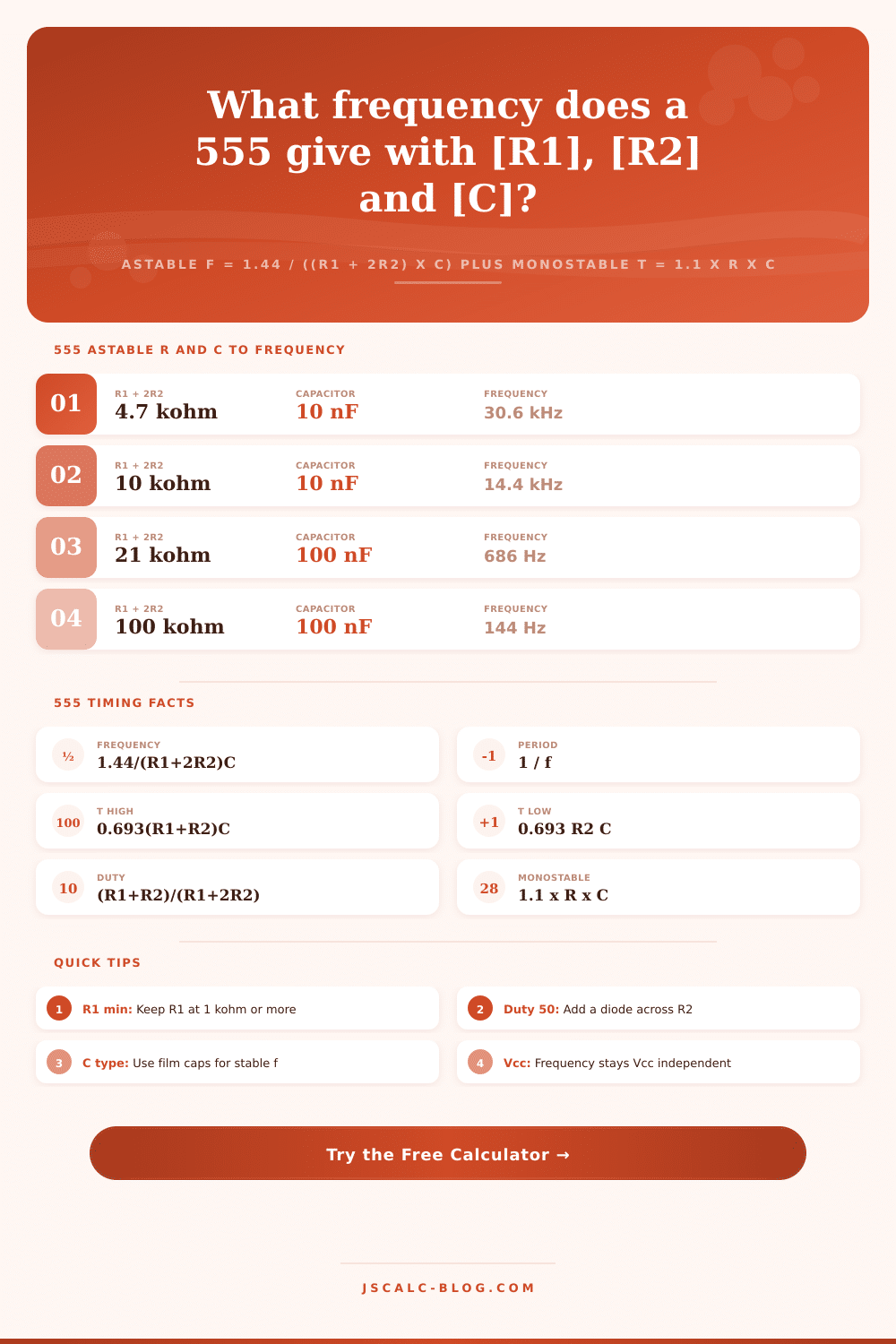
| 1 kohm | 10 kohm | 100 nF | 686 Hz | 52.4% |
| 10 kohm | 10 kohm | 100 nF | 480 Hz | 66.7% |
| 4.7 kohm | 4.7 kohm | 10 uF | 10.2 Hz | 66.7% |
| 1 kohm | 68 kohm | 10 uF | 1.05 Hz | 50.4% |
| 3.3 kohm | 3.3 kohm | 100 uF | 1.45 Hz | 66.7% |
| 1 kohm | 6.8 kohm | 10 nF | 10.2 kHz | 53.4% |
| 2.2 kohm | 10 kohm | 1 uF | 65.2 Hz | 54.9% |
| 1 kohm | 2 kohm | 100 pF | 2.88 MHz | 60.0% |
🧮Duty Cycle vs R1 to R2 Ratio
| R1 : R2 Ratio | R1 + R2 | R1 + 2R2 | Duty Cycle | Character |
|---|---|---|---|---|
| 1 : 100 | 101 | 201 | 50.2% | Near square |
| 1 : 10 | 11 | 21 | 52.4% | Almost even |
| 1 : 5 | 6 | 11 | 54.5% | Slightly high |
| 1 : 2 | 3 | 5 | 60.0% | Wider high |
| 1 : 1 | 2 | 3 | 66.7% | Classic 2/3 |
| 2 : 1 | 3 | 4 | 75.0% | Long high |
| 5 : 1 | 6 | 7 | 85.7% | Narrow low |
| 10 : 1 | 11 | 12 | 91.7% | Brief low |
📐Capacitor Unit Conversions
| Value | In pF | In nF | In uF |
|---|---|---|---|
| 100 pF | 100 pF | 0.1 nF | 0.0001 uF |
| 1 nF | 1000 pF | 1 nF | 0.001 uF |
| 10 nF | 10000 pF | 10 nF | 0.01 uF |
| 100 nF | 100000 pF | 100 nF | 0.1 uF |
| 1 uF | 1000000 pF | 1000 nF | 1 uF |
| 10 uF | 10 M pF | 10000 nF | 10 uF |
🔌555 Pinout and Spec Reference
| Pin | Name | Function | Typical Note |
|---|---|---|---|
| 1 | GND | Ground reference | 0 V common |
| 2 | Trigger | Starts timing below 1/3 Vcc | Active low input |
| 3 | Output | Drives load high or low | Up to 200 mA |
| 4 | Reset | Forces output low when low | Tie to Vcc if unused |
| 5 | Control | Adjusts internal 2/3 Vcc ref | 0.01 uF to GND |
| 6 | Threshold | Ends timing above 2/3 Vcc | Sensed at cap top |
| 7 | Discharge | Open collector to discharge C | Sinks through R2 |
| 8 | Vcc | Positive supply | 4.5 to 15 V bipolar |
🗃Astable vs Monostable Comparison Grid
| Attribute | Astable Mode | Monostable Mode | Key Formula | Trigger Source | Typical Use |
|---|---|---|---|---|---|
| Behavior | Free-running | Single pulse | f vs t | Self / external | Clock vs delay |
| Resistors | R1 and R2 | Single R | R1+2R2 vs R | N/A | Oscillate vs one-shot |
| Output | Continuous train | One high pulse | Duty cycle vs width | Threshold vs trigger | Blink vs timeout |
| Timing law | 1.44/(R1+2R2)C | 1.1 x R x C | Frequency vs width | Auto vs pin 2 | Tone vs button timer |
| Rest state | Never rests | Output low idle | T vs t | Loop vs edge | Siren vs relay pulse |
| Retrigger | Not applicable | Ignored while high | Steady f vs fixed t | Cycle vs falling edge | PWM vs debounce |
| Duty range | Above 50% | Not defined | (R1+R2)/(R1+2R2) | Internal cap | LED vs alarm |
| Adjust rate | Vary R or C | Vary R or C | Both scale RC | Same cap network | Speed vs duration |
⚙Formula Breakdown
💡555 Design Tips
Inexpensive: The 555 timer is cheap, but it also has lots of application. Want to create a precise pulse generator for a hobbyist robot? No problem. Need a basic LED blinker for that school project? Piece of cake.
How does it work: To make a timer, all you realy need are some resistors and capacitors. Those component charge quickly through resistors and then slow down when they “top out” due to capacitance. That’s the math, which can be confusing at first. It’s one thing to read it, but quite another to watch the numbers update in real time. The above calculator does the dirty work while you concentrate on building something. Understanding what those inputs mean in terms of your circuit and why some combination behave differently than others should be enough to get started.
How to Use the 555 Timer Calculator
When configured for astable operation, the chip simply charges and discharges a capacitor to one of two fixed voltages, producing a constant square wave. When the capacitor is full, current flow through R1 and R2 and keeps the output high. As soon as it’s emptied out via R2 only, it switch back low again. That asymmetry is why all of the timing decisions you’ll end up making are based off this. Since there are two resistors in the charge path, the high portion of the cycle is always longer then the low portion. So your duty cycle will automatically be greater than 50% without any additional components to force it otherwise. It is a tiny physical quirk that catches almost everybody the very first time they try to produce a perfect square wave.
This whole thing fits on one line: That’s the frequency formula. To find out how many times something happen every second, you just divide 1.44 by whatever capacitance times whatever resistance value there is. That’s it. The calculator breaks it down so you can see exact time it spends high versus low and the interval for each. It then gives you duty cycle as a percent. Having those four numbers in front of you makes it easy to notice any issues without even needing to solder anything up yet.
For example, if you’ve got a duty cycle all wonky, you know instantly that you need R1 to be much bigger than R2. Or maybe your frequency isn’t very stable, which leads you to check whether or not your capacitor tolerance is stealing some of your timing budget. The formulas go from math equations to real-world limits.
Reality begins where the theory ends: picking out real components. While some ranges of resistance are fine, others will cause issues when it comes to leakage and current limits. Anything less than about a kilohom should of been avoided for R1 so the internal discharge transistor doesn’t have to sink too much current on the low phase. Using very small ceramic capacitors (down around pF) is great for high speed clocks or audio tones, but their extremely low value makes it hard to provide stable timing at really low frequencies, where pushing resistors into the megohm range can introduce noise sensitivity and capacitor leakage errors. At the opposite end, large electrolytic or film capacitors can do a good job at maintaining accurate timing for delays or slow blinks, but now add some physical bulk to your board. The reference table in each tool pairs common component values with their corresponding frequency, taking the guesswork out of finding a ballpark estimate whenever you’re looking for something quickly.
But if perfect half-duty-cycle operation is essential for some reason, then tweak it. To do so, simply add a diode across R2, which will cause the charging current to bypass that resistor entirely, leaving only R1 in the charge path. When R1 matches R2, you’ll get a true square wave with equal-on, equal-off time. This is a classic move that all electronics hobbyist learn very early on. Keep the diode trick in mind when you need more symmetry than the basic chip can provide on its own; the calculator is just doing what it usually does.
The other side of the story is monostable mode which is initiated with a single trigger pulse, then keeps the output high for a period of time before returning it low again. In this case, the pulse width is controlled by the same constant as above but with a slightly different equation involving only one resistor and capacitor. This is great for building basic delays, like wanting something to occur after a set amount of time once and only once, or debouncing a switch. There’s not a continuous wave here so you’re not worried about duty cycle at all. It’s simply a single timed event. Knowing that will allow you to select the correct configuration for what you need instead of trying to force one into every situation.
That’s why the 555 is still so popular despite its flaws: it works when you want it to work, which makes all the difference. After you learn the magic of timing that comes from R1, R2, and C, you’ll be able to set whatever frequency on the fly without doubt. You can play with the calculator, do quick iterations, and check your gut feelings. If you need something dead-on accurate or you’re building an LED flasher for kicks, understanding where every number fits lets you have a say in what happens. And that’s realy what engineering is about, taking away the guessing game, one cycle at a time.