Crystal Oscillator Load Capacitance Calculator
Match the two external capacitors on a Pierce oscillator using CL = (C1 x C2)/(C1 + C2) + Cstray. Find the load capacitance your crystal actually sees, size the symmetric caps C1 = C2 to hit its specified CL, and estimate the frequency pulling error in ppm and Hz from the shunt and motional capacitance.
⏲Choose a Mode
🎯Real Oscillator Presets
📝Crystal & Circuit Inputs
Datasheet target load, often 8 to 20 pF.
Trace, pad and pin capacitance per leg, 2 to 5 pF.
External cap from XTAL1 pin to ground.
External cap from XTAL2 pin to ground.
Marked frequency; used for the Hz error output.
Static parallel capacitance of the crystal.
Series-arm capacitance in femtofarads; drives pulling.
Controls rounding on the result cards.
🔢Formula Snapshot
📋Typical Load CL by Crystal Type
| Crystal / Application | Frequency | Typical CL | Notes |
|---|---|---|---|
| Watch / RTC tuning fork | 32.768 kHz | 6 to 12.5 pF | Low drive, high Q |
| Ultra low CL AT-cut | 8 to 40 MHz | 8 pF | Small pin caps |
| Low CL general | 4 to 50 MHz | 10 pF | Common SMD part |
| USB / MCU standard | 8 to 25 MHz | 12.5 pF | Very widespread |
| Legacy through-hole | 1 to 20 MHz | 16 pF | Older HC-49 cans |
| Classic microcontroller | 4 to 24 MHz | 18 pF | AVR / PIC default |
| High CL / robust | 1 to 30 MHz | 20 pF | Tolerant of stray |
| Fundamental HF can | 20 to 50 MHz | 20 to 30 pF | Check drive level |
📊Symmetric Cap Lookup (C1 = C2)
| Spec CL | Cstray 2 pF | Cstray 3 pF | Cstray 5 pF | Formula |
|---|---|---|---|---|
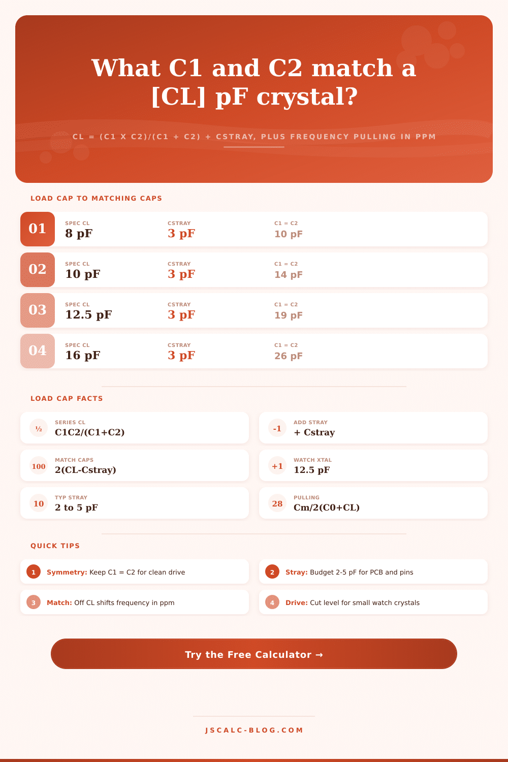
| 8 pF | 12 pF | 10 pF | 6 pF | 2(CL − Cs) |
| 10 pF | 16 pF | 14 pF | 10 pF | 2(CL − Cs) |
| 12.5 pF | 21 pF | 19 pF | 15 pF | 2(CL − Cs) |
| 16 pF | 28 pF | 26 pF | 22 pF | 2(CL − Cs) |
| 18 pF | 32 pF | 30 pF | 26 pF | 2(CL − Cs) |
| 20 pF | 36 pF | 34 pF | 30 pF | 2(CL − Cs) |
| 22 pF | 40 pF | 38 pF | 34 pF | 2(CL − Cs) |
📏Stray Capacitance Budget Guidance
| Contributor | Typical Value | Range | Layout Note |
|---|---|---|---|
| MCU oscillator pin | 2 pF | 1 to 5 pF | Read pin CL in datasheet |
| Short PCB trace | 1 pF | 0.5 to 2 pF | Keep tracks under 10 mm |
| Pad and via | 0.5 pF | 0.3 to 1 pF | Minimize copper area |
| Ground guard ring | 0.5 pF | 0.2 to 1 pF | Adds but cuts noise |
| Total typical Cstray | 3 pF | 2 to 5 pF | Use per single leg |
| Loose long-trace layout | 5 to 7 pF | up to 10 pF | Avoid; degrades CL match |
🗃Crystal Parameter Comparison Grid
| Crystal Type | Frequency | Spec CL | Max ESR | C0 Shunt | Cm Motional | Drive Level | Tolerance |
|---|---|---|---|---|---|---|---|
| Watch tuning fork | 32.768 kHz | 12.5 pF | 50 kΩ | 1.35 pF | 3 fF | 1 µW | ±20 ppm |
| RTC low CL | 32.768 kHz | 6 pF | 70 kΩ | 1.1 pF | 2.5 fF | 0.5 µW | ±20 ppm |
| Low CL SMD | 12 MHz | 10 pF | 80 Ω | 2.5 pF | 12 fF | 100 µW | ±30 ppm |
| USB / MCU | 16 MHz | 12.5 pF | 50 Ω | 3 pF | 10 fF | 100 µW | ±30 ppm |
| Classic MCU | 8 MHz | 18 pF | 60 Ω | 3.5 pF | 14 fF | 200 µW | ±50 ppm |
| Ethernet PHY | 25 MHz | 18 pF | 40 Ω | 4 pF | 9 fF | 200 µW | ±50 ppm |
| CAN node | 20 MHz | 20 pF | 30 Ω | 4 pF | 8 fF | 300 µW | ±30 ppm |
| HF fundamental | 40 MHz | 20 pF | 30 Ω | 5 pF | 6 fF | 300 µW | ±50 ppm |
⚙Formula Breakdown
💡Load Capacitor Design Tips
Is it oscillating like an out-of-tune orchestra? Your microcontroller won’t lock. You’ve used the right part number. You can read the schematic and everything seems right. You’ve even taken special care to solder every joint. The system doesn’t enumerate or worse yet, it’s drifting out of time by several seconds per hour.
Don’t blame the chip. Rarely is this a bad chip. Nine times out of ten, it’s a capacitor problem: specifically, sizing your capacitors in relationship to stray capacitance on your pins and traces. This calculator will do the math for you, no more guessing why your oscillator are running at the wrong frequency.
Why Your Clock Is Wrong
The thing about a quartz crystal is that it’s not going to vibrate at one fixed frequency; rather, it behaves as a parallel shunt capacitor with a high-Q series resonant circuit with a motional arm. Only if it is loaded with a certain amount of capacitance across its terminals will it start to oscillate on its marked frequency. That capacitance is known as load capacitance or CL. If you apply the incorrect value there, it’ll run the oscillator, but pull it off spec. A couple of tens of parts per million may not sound significant, but it’s enough to blow up a real-time clock or fubar USB timing.
You need to stop and think about exactly what is connected. On each side of crystal are two grounded capacitors in a typical Pierce oscillator. As far as the crystal sees them, those two capacitors appear in series with each other. What does that mean? You know how if you have two capacitors in series then their series equivalent is the product divided by the sum? Well, not quite. There is always some stray capacitance involved: from the traces and pads and pins that electrically connect the crystal to the capacitors. And that stray capacitance are part of the series circuit that the crystal “sees.” The full expression the crystal experiences is the series combination of your two caps plus that stray value.
If there were 3pF of capacitance on each leg, and your two capacitors was both 30 pF, then together they’d be 15 pF in series. Add the stray and the crystal sees 18pF. This is perfect for a common spec on a microcontroller.
Capacitors are symmetric in most designs; C1 = C2. This provides a balanced drive of the oscillator loop and the cleanest start up behavior. If you make both caps C then math simplifies nicely, and it’s half that plus stray capacitance to the crystal. To find the right capacitor value for a spec CL, solve for the capacitor first. Take twice the difference from the spec CL and subtract the stray capacitance you expect on each side.
That’s where folks go awry. They forget to account for the stray capacitance and just double the spec. This results in a capacitor that is too large and pulls frequency down. For beginners: Stray capacitance is the term they forget, while experts obsess over it. This is mostly between 1 and 5 pF from the oscillator input pin of the chip itself; add in the ground guard ring around the crystal, as well as pads, vias, and copper traces connecting everything together, and you can expect to have roughly 3 pF per leg in a compact layout. This parasitic effect is added right into the load, so if you ignore it your design will slowly wander away.
The calculator shows how far you are off. In both hertz and parts-per-million, or ppm. By assuming motional and shunt capacitance numbers from the datasheet it provides a reasonable guess at that change, with something to stand behind. You don’t need to learn this to use the tool; just know that the ratio between motional capacitance and total load determines the device’s sensitivity. In particular, watch crystals at 32.768 kHz has extremely small motional capacitance, around 3 fF, which makes them very sensitive to their load. This explains the fussiness of an RTC layout in terms of component placement.
As you move up in frequency, the pull becomes gentler, but when you’re after narrow tolerances, every picofarad matters. From 16 MHz microcontrollers to 25 MHz Ethernet references, the preset buttons on the page cover what engineers encounter most frequentley. Select the closest preset to your design, tweak the stray capacitance to fit your board layout, then read the results. You’ll get the estimated frequency shift, the capacitance error, the recommended symmetric cap value for hitting spec, and even the actual load that will be seen by the crystal. It turns the abstract series-load formula into quick and reliable numbers you can trust.
But you know, one of the first things to get right is to get your caps right. And to do that is to get your clock right when you factor in what’s already there on the board before you add any other component from outside. Once you do that, you stop fighting the physics and work with them.
Small thing? Yes. But it matters.