Clock Divider Calculator
Divide any reference clock by an integer with fout = fin / N, cascade two stages as fin / (N1 x N2), or enter a target output frequency and var the tool solve the nearest divider. Every result reports the output frequency, the actual versus desired error, the counter bits required, the output period, and the duty-cycle you can expect from that value of N.
⏳Choose a Division Mode
🎯Real Clock Divider Presets
📝Clock and Divider Inputs
The reference clock feeding the divider chain.
Applies to the input clock field above.
Whole number the clock is divided by, N ≥ 1.
First cascaded prescaler stage.
Second stage; total ratio is N1 x N2.
Target the tool matches with the nearest integer N.
Unit for the desired output frequency.
Controls rounding on every result card.
🔢Formula Snapshot
📋Common Divider Values, Ratio and Bits
| Divide N | Ratio fin : fout | Counter Bits | Duty at 50% | Typical Use |
|---|---|---|---|---|
| 2 | 1 : 2 | 1 bit | Yes, even | Toggle flip-flop |
| 4 | 1 : 4 | 2 bits | Yes, even | Quarter-rate clock |
| 8 | 1 : 8 | 3 bits | Yes, even | Byte-timing prescale |
| 10 | 1 : 10 | 4 bits | Yes, even | Decade counter |
| 16 | 1 : 16 | 4 bits | Yes, even | UART oversampling |
| 32 | 1 : 32 | 5 bits | Yes, even | Slow peripheral clock |
| 256 | 1 : 256 | 8 bits | Yes, even | Timer prescaler |
| 1024 | 1 : 1024 | 10 bits | Yes, even | Watchdog / RTC prescale |
| 65536 | 1 : 65536 | 16 bits | Yes, even | Full 16-bit counter roll |
📊Binary Counter Stages and Max Divide
| Counter Bits | Max Modulus 2^n | Max Divide N | Toggle Output | Example Part Style |
|---|---|---|---|---|
| 1 | 2 | 2 | fin / 2 | Single D flip-flop |
| 2 | 4 | 4 | fin / 4 | 2-bit ripple counter |
| 3 | 8 | 8 | fin / 8 | 3-bit binary counter |
| 4 | 16 | 16 | fin / 16 | 74x161 style |
| 7 | 128 | 128 | fin / 128 | 7-bit ripple |
| 8 | 256 | 256 | fin / 256 | 8-bit timer/counter |
| 12 | 4096 | 4096 | fin / 4096 | 12-stage 4040 style |
| 16 | 65536 | 65536 | fin / 65536 | 16-bit timer |
| 24 | 16777216 | 16777216 | fin / 16.7M | 24-bit accumulator |
🔧Prescaler Examples: Baud and Timers
| Application | Input Clock | Divider N | Output | Notes |
|---|---|---|---|---|
| UART 9600 x16 | 1.8432 MHz | 12 | 153.6 kHz | 16x baud tick, exact |
| UART 115200 x16 | 1.8432 MHz | 1 | 1.8432 MHz | 16x oversample clock |
| Timer0 tick | 8 MHz | 8000 | 1 kHz | 1 ms system tick |
| Timer prescale /64 | 16 MHz | 64 | 250 kHz | Classic AVR prescaler |
| SPI SCK | 48 MHz | 48 | 1 MHz | Master clock divide |
| I2C fast mode | 16 MHz | 40 | 400 kHz | Bit-rate generator |
| Audio MCLK to LRCK | 12.288 MHz | 256 | 48 kHz | 256 fs I2S ratio |
🗃MCU and FPGA Clock-Source Comparison Grid
| Clock Source | Typical fin | Divider Depth | PLL On-Chip | Output Range | Common Use Case |
|---|---|---|---|---|---|
| 8-bit AVR MCU | 16 MHz | up to /1024 | No | 15.6 kHz - 16 MHz | Timer and UART prescale |
| ARM Cortex-M0 | 48 MHz | up to /512 | Yes | 93.75 kHz - 48 MHz | Peripheral clock trees |
| ARM Cortex-M4 | 168 MHz | up to /512 | Yes | 328 kHz - 168 MHz | Bus and timer domains |
| ESP32 SoC | 240 MHz | up to /8192 | Yes | 29 kHz - 240 MHz | APB and RMT dividers |
| RTC crystal | 32.768 kHz | up to /32768 | No | 1 Hz - 32.768 kHz | Real-time 1 Hz second |
| Lattice iCE40 FPGA | 48 MHz | fabric counter | Yes | sub-Hz - 48 MHz | Custom counter dividers |
| Xilinx 7 Series FPGA | 100 MHz | MMCM / counter | Yes | sub-Hz - 100 MHz+ | Pixel and link clocks |
| Intel Cyclone FPGA | 50 MHz | PLL + counter | Yes | sub-Hz - 50 MHz+ | Logic and I/O clocks |
⚙Formula Breakdown
💡Clock Divider Design Tips
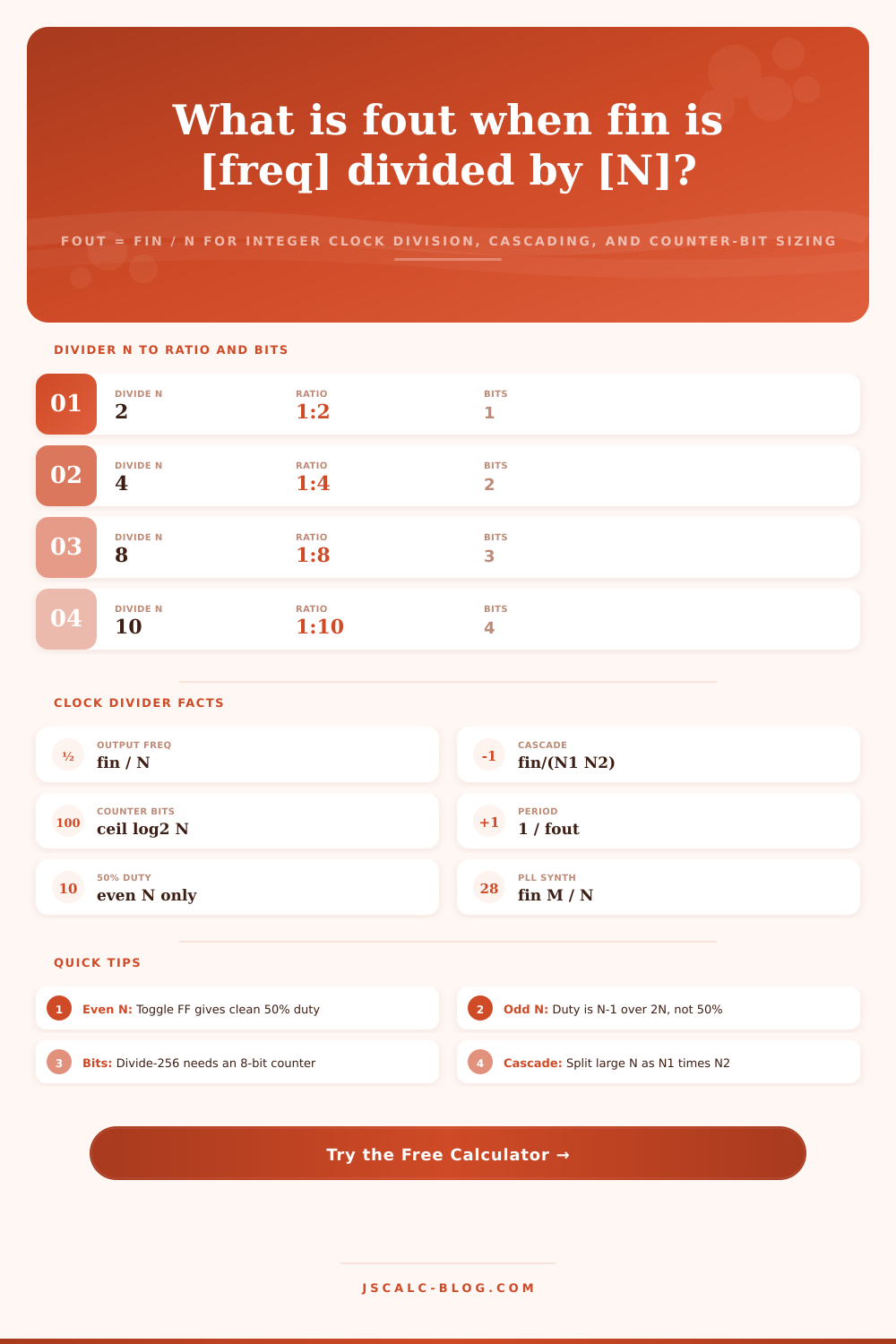
The clock divider creates a slower clock from a faster one, at an exact whole number ratio. The underlying formula is straightforward: fout = fin / N. In this formula, fin is the input frequency. N is integer value of division factor. Fout is the output frequency produced. So this tool will work backwards through that to solve three cases: you can plug in fin and N yourself, or provide a target fout and have the tool compute the closest matching N (with the result reported as its percent error), or you can put in a stage of cascaded dividers where resulting ratio is product of two factors N1 x N2. Along with output frequency, the tool will report back the duty cycle you should expect, the output period, and how many bits are needed on your counters to implement it.
Almost every digital system runs on one or two high-speed reference clocks, yet its peripherals need many slower rates. For example, a microcontroller might boot off a 16 MHz crystal driving a 1 MHz SPI bus and a 400 kHz I2C link along with a 115200 baud UART and a 1 kHz system tick simultaneously. Instead of having a dedicated oscillator for each rate, designers divide the master clock down to derive these rates. Since integer division can be implemented as a chain of flip-flops counting input edges and asserting the output every N cycles, it’s inexpensive. The fact that fout = (fin/N) is deterministic and jitter-free compared to fin makes it the basis for baud-rate generators, timer prescalers and the clock tree in every FPGA and MCU.
How to Use the Clock Divider Tool
Let’s begin at top of page with the one-divider mode. The tool will take an input clock, which you specify in units ranging from Hz to GHz, then you select integer N. You get back fout, simply by dividing in. For example, 16 MHz / 16 = 1 MHz. Or a 100 MHz FPGA clock / 4 = a 25 MHz pixel clock for VGA. Note that Tout = 1/fout is also reported by the tool, which automatically scales into seconds, milliseconds, microseconds, or nanoseconds. So we see 1 Hz out is 1 second, while our 25 MHz out is 40 nanosecundes. If you think about it, the possible range of values you can achieve are discrete since N must be an integer. That’s precisely why we have target-solver mode.
Smaller stages can form large divides. If you put two dividers in sequence, they’ll have a ratio equal to product of each. So fout = fin / (N1 * N2). You can also enter them in cascade mode where it tells you the combined N, which is useful for more than just math. Breaking down a divide-by-1000 into 125 times 8 (or divide-by-256 into 16 times 16) means that each stage will handle a lower frequency than the previous one. This relaxes timing requirements and reduces number of flip-flops required to implement each stage within an FPGA or ASIC fabric. And it reflects how actual prescalers are physically implemented, a wide but slow back-end counter preceded by a narrow but fast front-end stage.
On occasion you’ll just have to know what frequency you get. In this case (the target mode), you tell it your desired output. It calculates N as the rounded value of fin divided by ftarget, then uses that integer to recalculate fout. It also tells you percent error, which is important: integer division rarely hits an arbitrary target exact. Ask your 16 MHz clock for 400 kHz and N = 40 lands right on the nose. Ask for 300 kHz and N = 53 is closest, yielding approximately 301.9 kHz. That’s not nothing, and if you’re doing something critical, that’s a number you should of seen before you commit. That’s where a fractional-N PLL works well, and that’s where a simple divider shows its limitations.
A modulo-N counter requires as many flip-flops (aka state) as there are N states. The number of bits required follows the rule: bits equals the smallest integer greater than or equal to log base 2 of N. One bit is all that’s needed for a divide-by-2; 8 bits for divide-by-256; 10 bits for divide-by-1024. See? The ceiling for a divide-by-1000 requires 10 bits too, since nine bits only go up to 512. Hardware guys gets this printed out on a separate card to help them size their counter register. Software guys check it against their prescaler value to make sure it’ll fit into a 16-bit or 8-bit timer.
The surprise to new users is that not all dividers provide a clean square wave. If you divide by an odd number using a simple modulo-N counter, the result isn’t a 50% duty cycle (on for half the time and off for the other half): it’s high for (N; 1) / 2N of the period. Divide-by-5 isn’t 50%, it’s 40%! The calculator reports expected duty cycle for your chosen N. The tips also describe how you can use an extra divide-by-2 stage to restore symmetry if you need to divide by an odd ratio in order to use a balanced clock.
If there’s no integer divider that will get us to the number we want, then the engineer turns to a phase-locked loop, which does division and multiplication at once: fout = (fin) × (M/N). A PLL feeds back part of the frequency, multiplying by M but dividing by N; together they synthesizes frequencies not at the discrete steps that an integer divider can create. This is how we get an odd-numbered pixel or serial-link rate out of a 100 MHz board clock. Because this covers most counter and prescaler designs, it leaves the integer divider as default model of the calculator. It also records the PLL relationship in case you need to bump up to a synthesizer.
Four result cards sum up output frequency, frequency error relative to your target, counter bits, and output period. A breakdown panel replaces your values in all of those equations so that you can use it as a sanity check on your own calculations. Presets pull in real world scenarios from day-to-day embedded work. This covers everything from creating a 48 kHz audio sample rate from a 12.288 MHz master clock at the standard 256 fs ratio to converting a 32.768 kHz watch crystal into a 1 Hz real-time-clock second. There is something for every level of digital counter knowledge. Students can learn, firmware engineers can set their timer prescalers, and FPGA developers can build a clock enable. This turns fout equals fin over N into quick and verifiabel answers.