Potentiometer Voltage Divider Calculator
Enter the total pot resistance, wiper rotation, taper and input voltage to get the wiper output voltage, both ideal and loaded, along with the resistance above and below the wiper. Compare linear, logarithmic (audio) and anti-log tapers on the same knob position.
🎯Real Potentiometer Presets
🔧Potentiometer Inputs
End to end track value of the potentiometer.
Applies to Rt and the load resistance below.
0% is fully counter clockwise, 100% is fully clockwise.
How resistance changes across the rotation arc.
Voltage across the full track, top pin to bottom pin.
Input resistance of the next stage. Use a large value for none.
Controls how aggressive the log and anti-log curves are.
Rounding applied to voltage and resistance cards.
🔢Formula Snapshot
📋Rotation vs Wiper Voltage by Taper
| Rotation | Fraction Linear | Fraction Log | Vwiper Linear (9 V) | Vwiper Log (9 V) |
|---|---|---|---|---|
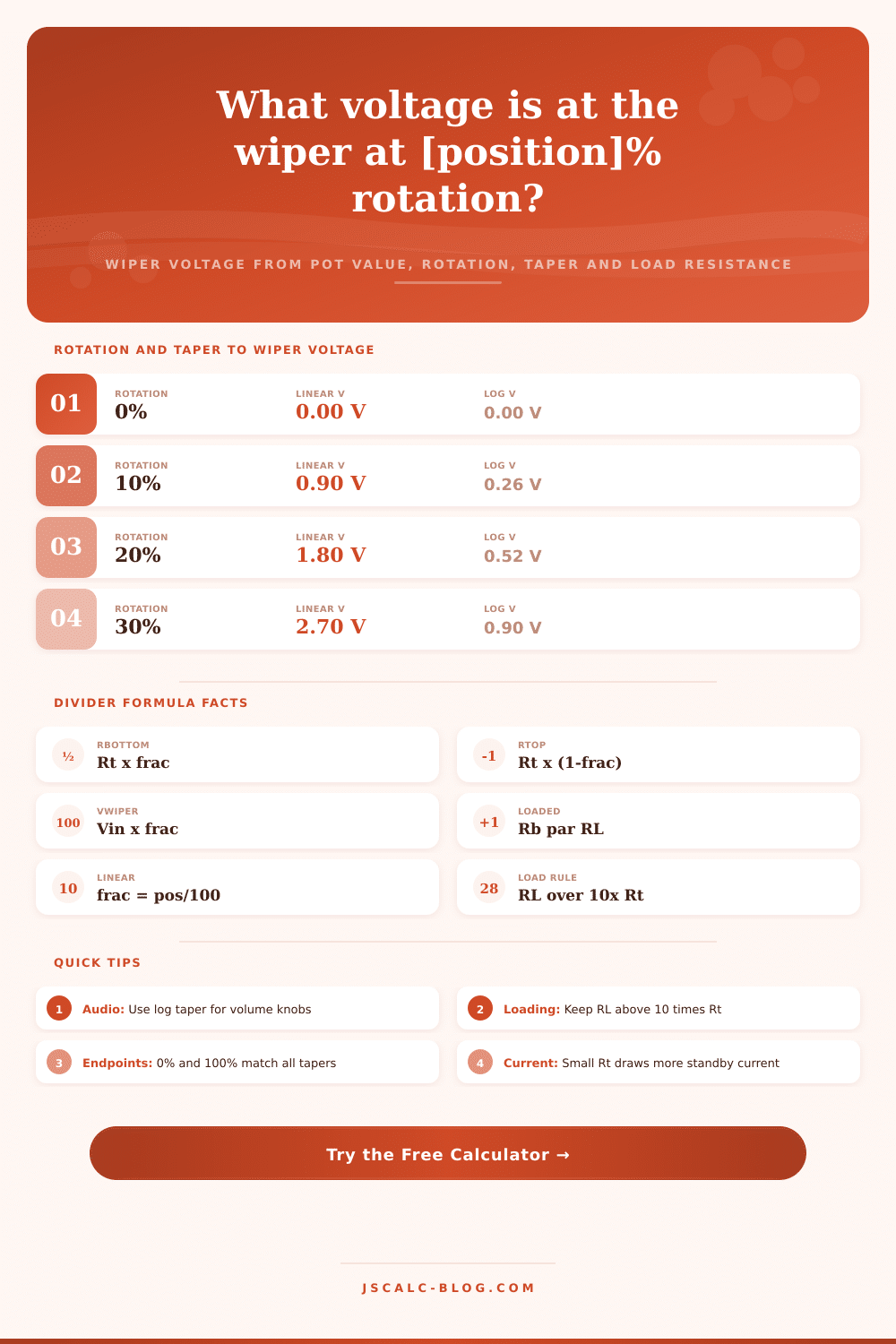
| 0% | 0.000 | 0.000 | 0.00 V | 0.00 V |
| 10% | 0.100 | 0.029 | 0.90 V | 0.26 V |
| 20% | 0.200 | 0.058 | 1.80 V | 0.52 V |
| 30% | 0.300 | 0.100 | 2.70 V | 0.90 V |
| 40% | 0.400 | 0.151 | 3.60 V | 1.36 V |
| 50% | 0.500 | 0.240 | 4.50 V | 2.16 V |
| 60% | 0.600 | 0.366 | 5.40 V | 3.29 V |
| 70% | 0.700 | 0.532 | 6.30 V | 4.79 V |
| 80% | 0.800 | 0.754 | 7.20 V | 6.79 V |
| 100% | 1.000 | 1.000 | 9.00 V | 9.00 V |
🎚Common Pot Values and Standby Current
| Pot Value | Rbottom at 50% | Rtop at 50% | Current at 9 V | Typical Use |
|---|---|---|---|---|
| 1 k | 500 | 500 | 9.00 mA | Low noise trim |
| 5 k | 2.5 k | 2.5 k | 1.80 mA | Fan and motor speed |
| 10 k | 5 k | 5 k | 0.90 mA | Audio volume |
| 50 k | 25 k | 25 k | 0.18 mA | Tone and blend |
| 100 k | 50 k | 50 k | 0.09 mA | Bias and gain trim |
| 500 k | 250 k | 250 k | 18 uA | Guitar tone |
| 1 M | 500 k | 500 k | 9 uA | High impedance ref |
⚖Loading Effect on the Wiper
| RL vs Rt Ratio | Example (10k pot) | Ideal V at 50% | Loaded V at 50% | Sag |
|---|---|---|---|---|
| 0.1x | RL = 1 k | 4.50 V | 1.29 V | Severe |
| 0.5x | RL = 5 k | 4.50 V | 3.00 V | Heavy |
| 1x | RL = 10 k | 4.50 V | 3.60 V | Noticeable |
| 2x | RL = 20 k | 4.50 V | 4.09 V | Mild |
| 5x | RL = 50 k | 4.50 V | 4.33 V | Small |
| 10x | RL = 100 k | 4.50 V | 4.41 V | Minor |
| 100x | RL = 1 M | 4.50 V | 4.49 V | Negligible |
🗃Rotation, Taper and Load Comparison Grid
| Rotation | Taper | Rbottom (10k) | Vwiper Ideal | Vwiper Loaded | Notes |
|---|---|---|---|---|---|
| 25% | Linear | 2.5 k | 2.25 V | 2.05 V | Even scale |
| 25% | Log | 0.77 k | 0.69 V | 0.65 V | Quiet start |
| 50% | Linear | 5 k | 4.50 V | 3.60 V | Midpoint |
| 50% | Log | 2.4 k | 2.16 V | 1.96 V | Ear linear |
| 50% | Anti-log | 7.6 k | 6.84 V | 5.92 V | Fast rise |
| 75% | Linear | 7.5 k | 6.75 V | 5.03 V | Upper range |
| 75% | Log | 4.9 k | 4.41 V | 3.53 V | Catching up |
| 90% | Linear | 9 k | 8.10 V | 4.74 V | Near top |
| 90% | Log | 7.4 k | 6.63 V | 4.20 V | Steep climb |
| 100% | Any | 10 k | 9.00 V | 4.29 V | Full output |
⚙Formula Breakdown
💡Potentiometer Wiring Tips
When you twist a volume knob, you want the sound to gradually grow from barely audible to ear-splitting loud. But instead, it’s completely silent until three-quarters of the way around, then blows out your eardrums with one last tick. That’s the traditional mis-match between our sense of hearing and action of most low-cost potentiometers.
What is the missing link between turning a physical lever and receiving an electric signal? The potentiometer voltage divider calculator found on this page answer that question. For every degree of rotation, the calculator provide the precise voltage on the wiper pin. It takes into account both the taper curve and loading caused by whatever comes next in your circuit. No more scribbling complex logarithms on cocktail napkins, no more muffled mixes or reluctant dimmers! Let the calculator crunch the math while you enjoy the tactile sensation of adjusting something.
How a Potentiometer Voltage Divider Works
Imagine a pair of resistors with their ends connected together via the wiper. If we call them Rtop (the part above the wiper) and Rbottom (the bit below), then regardless of where the wiper is positioned Rtop + Rbottom = Rt, the total resistance of the track. That’s because you can think of the resistive track as being two resistors in series one above the other.
Since the voltage on the wiper is just the input voltage (Vin), scaled-down according to how much of the track is below it, the wiper voltage is Vin times (Rbottom/Rt). Put another way, if you consider the resistance below the wiper to be Rbottom, which is a fraction of Rt, then the ideal wiper voltage will be Vin times that fraction. Turning the shaft alters what fraction Rbottom is compared too Rt, which alters the output. Simple enough except for pesky real world stuff like loads and perception.
A potentiometer differs from a plain fixed divider in two ways. First, it is tapered, which affects the relationship between resistance fraction and rotation angle. Second, it work differently. A linear pot (marked B) gives you the fraction as it’s turned. At 50%, the track divides equally into top and bottom halves, so Rt is twice Rbottom.
With a logarithmic or audio pot (marked A), the relationship bends: turn it through half its range, and the modelled log law shows that you get much less then half the voltage out. This is because human hearing responds to sound approximately on a logarithmic scale: each step up corresponds not to adding the previous signal level but multiplying by a constant factor. Place a linear pot onto your volume control, and you will hear that the sound is bunched up near the end of the rotation while the bottom half sounds nearly silent.
The log taper reverses this by starting slow and accelerating gradually towards its final resistance so the ear interprets it as an evenly ramping smoothness. It’s why looking at that knob turning isn’t as important as understanding what it represents as a fraction.
An ideal divider assumes nothing draws current from the wiper, but real circuits connect the wiper to a following stage that has its own input resistance, called the load RL. Instead of zero, the bottom leg of the circuit now includes both Rbottom and this load in parallel. It’s this loading that many builders fail to consider.
If your load is significant, it will pull the output down toward ground, changing the shape of the taper (making a log pot appear more linear, or vice-versa). To compute the effect, the calculator combines Rbottom and RL in parallel for the effective bottom leg, recalculates the divider, and compares results. You’ll see the loaded voltage sag compared to ideal.
A good rule of thumb is that you should of want your load to resist about 10X the amount the pot can hold so the curve stays true. For example if I have a 100 kilohm load and my pot is rated at 10 kilohms, then the middle point sags by less than 2%. If I have a one kilohm load on the same pot, it’s collapsed into a sorry mess.
With no wiper attached, it will draw whatever current corresponds to the total resistance set on the divider. The smaller ones is harder for whatever you attach to change, but they do this by loading down poor sources and wasting power. The larger ones sip current, but tend to be easily influenced by loads and grab more noise.
A good place to start is with the reference tables on the page that list popular resistor values between one kilohm and one megohm along with their standby current and typical applications. From there, you can see the tradeoffs and find the right balance for your application. Pick a starting point, tweak the inputs and let the numbers lead you to components.
It’s about more than simply getting voltage out; it’s about getting the right voltage at the right point so it does what you want. The position of the wiper represents a different thing based off the next component it connects to when you’re setting volume or adjusting bias trim. Lighten up the load, match the taper and finally your knobs will do what they claim.