PCB Via Current Calculator
Estimate the current-carrying capacity of a plated through-hole via using the IPC-2221 charts. Enter the finished hole diameter, copper plating thickness and allowable temperature rise, and the tool computes the barrel copper cross-section, the single-via ampacity, the total for vias placed in parallel and your design margin versus the current you plan to push.
⚡Real Via Stackup Presets
🔧Via and Load Inputs
Drilled and plated barrel inner diameter.
Applies to the hole diameter field above.
Barrel wall copper. 25 um is IPC Class 2 min, 34.79 um is 1 oz.
Conductor rise above ambient, typically 10 to 20 C.
Board environment; sets the final barrel temperature.
Vias sharing the same net to split the load.
Via barrels are usually treated as internal conductors.
Design load through the via or via group, for the margin card.
🔢Formula Snapshot
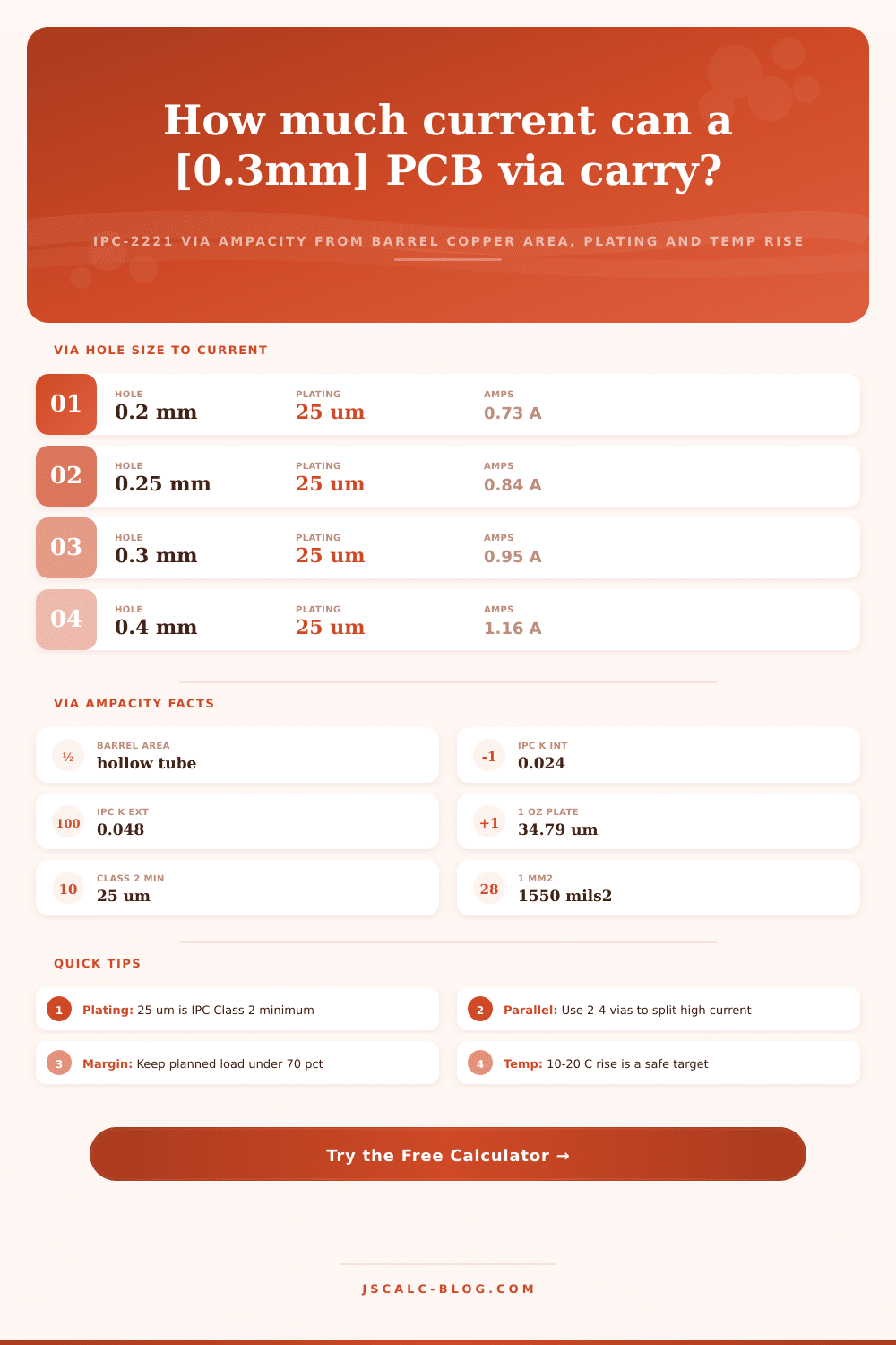
📋Hole Size to Current (25 um plating, dT 10 C)
| Finished Hole | Barrel Area | Internal Cap | External Cap |
|---|---|---|---|
| 0.15 mm (6 mil) | 0.0137 mm² | 0.61 A | 1.21 A |
| 0.20 mm (8 mil) | 0.0177 mm² | 0.73 A | 1.46 A |
| 0.25 mm (10 mil) | 0.0216 mm² | 0.84 A | 1.69 A |
| 0.30 mm (12 mil) | 0.0255 mm² | 0.95 A | 1.90 A |
| 0.40 mm (16 mil) | 0.0334 mm² | 1.16 A | 2.31 A |
| 0.50 mm (20 mil) | 0.0412 mm² | 1.35 A | 2.69 A |
| 0.60 mm (24 mil) | 0.0491 mm² | 1.53 A | 3.06 A |
| 0.80 mm (31 mil) | 0.0648 mm² | 1.87 A | 3.74 A |
🔧Plating Thickness Effect (0.3 mm hole, dT 10 C)
| Plating (um) | Copper Weight | Barrel Area | Internal Cap | External Cap |
|---|---|---|---|---|
| 12.5 um | ~0.36 oz | 0.0123 mm² | 0.56 A | 1.12 A |
| 17.5 um | ~0.50 oz | 0.0175 mm² | 0.72 A | 1.44 A |
| 20 um | ~0.57 oz | 0.0201 mm² | 0.80 A | 1.60 A |
| 25 um (Class 2) | ~0.72 oz | 0.0255 mm² | 0.95 A | 1.90 A |
| 34.79 um (1 oz) | 1.00 oz | 0.0366 mm² | 1.23 A | 2.47 A |
| 50 um | ~1.44 oz | 0.0550 mm² | 1.66 A | 3.32 A |
| 70 um (2 oz) | 2.01 oz | 0.0814 mm² | 2.20 A | 4.41 A |
🌡Temperature Rise Multiplier (0.3 mm, 25 um)
| Temp Rise dT | dT^0.44 Factor | Internal Cap | External Cap |
|---|---|---|---|
| 5 C | 2.03 | 0.70 A | 1.40 A |
| 10 C | 2.75 | 0.95 A | 1.90 A |
| 15 C | 3.28 | 1.14 A | 2.27 A |
| 20 C | 3.73 | 1.29 A | 2.58 A |
| 30 C | 4.44 | 1.54 A | 3.08 A |
| 40 C | 5.05 | 1.75 A | 3.50 A |
🗃Via Design Comparison Grid
| Application | Hole | Plating | Temp Rise | Single Cap | Vias | Total Cap |
|---|---|---|---|---|---|---|
| HDI signal via | 0.20 mm | 20 um | 10 C | 0.64 A | 1 | 0.64 A |
| Standard signal | 0.30 mm | 25 um | 10 C | 0.95 A | 1 | 0.95 A |
| BGA dogbone | 0.40 mm | 25 um | 15 C | 1.40 A | 1 | 1.40 A |
| Power feed | 0.50 mm | 35 um | 20 C | 2.35 A | 2 | 4.70 A |
| Thermal relief | 0.30 mm | 25 um | 20 C | 1.29 A | 4 | 5.16 A |
| Stitching field | 0.30 mm | 25 um | 10 C | 0.95 A | 9 | 8.55 A |
| Heavy copper rail | 0.50 mm | 70 um | 20 C | 3.61 A | 3 | 10.8 A |
| 1 oz supply via | 0.40 mm | 34.8 um | 15 C | 1.88 A | 3 | 5.64 A |
⚙Formula Breakdown
💡Via Ampacity Design Tips
Traveling through a barrel in a via means moving from one layer to another. That barrel is a very small tunnel of copper, and frequently the weakest link in your power network. Vias are constrained by plating thickness and hole size, while traces can get as wide as needed. Don’t rely on guessing if a single via is sufficient for your power rail; guess wrong and you’ll either overheat or create an open circuit that fails after months of use. Simply input your hole sizes into the calculator and let it crunch the numbers for you.
What’s a via? A completed via is actualy a hollow tube made when copper is plated on the inside of a drilled hole. But how do we determine the amount of copper in the wall of a via? The trick is that we must subtract the inside diameter from the outside diameter of the plated copper and divide that result into the area of the ring. The actual cross sectional area come from a ring around the hole where the copper has been added to the wall. Suppose you start with a typical 0.3 mm hole plated at the standard 25 microns. The total thickness of the wall contributes, but the cross sectional area is still pretty small. The area is about 0.025 square millimeters. That little band of copper has to carry all the current between layers. So this geometric calculation becomes important.
How to Use a Via Current Calculator
Luckily, the IPC-2221 standard gives us an unambiguous way to convert that area into amps. The formula relates the copper cross section and the allowed temperature rise to current carrying capacity with some very particular exponents. Because the via barrels are encapsulated in laminate, not air, they considers them to be internal conductors. This makes sense, because traces buried inside the board don’t radiate heat as well as those exposed to air on the board’s surface. Rather than having to remember which constant to apply for surface vs buried loss, the calculator uses the appropriate one for internal conduction. All you have to know is that the number it returns is calculated under a conservative thermal situation.
Now you may be asking yourself, what is the purpose of the parallel via count? Most of today’s power delivery isn’t going through a single little via. They puts multiple vias right next to each other. This distributes the current across several vias. The total capacity is additive so if there are four 1-amp vias, they can handle four amps together. That way, no single barrel gets too hot because it spreads the heat out in the surrounding copper planes. It is a simple solution that offers better reliability, less chance of local hot spots, and no need for huge hole drills that is difficult to make.
The thickness of the plating itself matters a lot too. Although 25 micron (micrometer) minimum plating are required by the IPC Class 2 standard, some designs is better served with thicker plating. Increasing plating thickness by a factor of two roughly doubles the copper surface area and greatly increases the current carrying ability. On the other hand, thick plating takes longer to electroplate and costs more, so you do have to balance cost against performance when making that decision. Fortunately, the tool comes with tables of reference data indicating the impact on current capacity due to plating thickness (e.g., switching from 25 to 50 microns) for typical hole diameters. From there, you can determine whether or not it’s worth spending extra for a thicker copper if you need to handle higher currents for your particular application.
The other adjustable variable is temperature rise. You can set it to allow for more current flow (which of course raises the heat) or you can run cooler. Usually running cooler is preferable as long as you don’t need the extra power; a 10 degree Celsius rise is generally safe for everyday operation while 20 degrees might be acceptable for transient loads. You can tweak that one too and check out your headroom for various situations. Better to err on the conservative side with a rise and keep headroom rather than run right up against the thermal limits. Ambient conditions and board plating vary from real board to board, so having some margin will protect your design from variation in production.
The takeaway: When designing with vias, consider the big picture, not each part in isolation. To find the best balance between your design requirements and available resources (e.g., budget), understand how to manage via count, hole size, plating thickness, and temperature limits. By using the presets included, which span everything from heavy power delivery to signal integrity applications, you can visualize the interaction of various parameters. Begin with a preset that aligns with your application, then adjust input values until reaching the ideal tradeoff. It’s a step-by-step process that transforms a vague thermal issue into a clear series of decisions.
There’s no magic number here; it’s all about giving respect to the physical limits of the copper barrel. The little tubes are so handy if sized properly, but they don’t stand up well to high loads. Use the calculator to check your margins before fabrication and save yourself the expense of having to redesign. Plan to keep your loads well below seventy percent of your calculations to accommodate any real-world imperfections. When that board finally goes out the door, that extra head room pays for itself in both peace of mind and reliablity.