Ohm's Law Voltage Drop Calculator
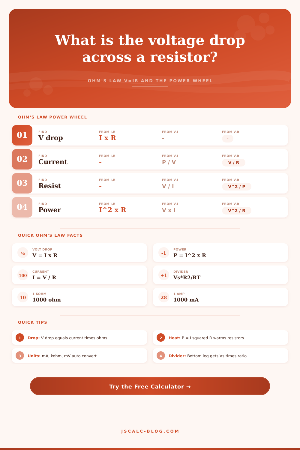
Solve voltage drop across a resistance with V = I × R and the power wheel P = V×I = I²×R = V²/R. Enter any two of voltage, current, resistance, or power, or switch to a series voltage divider.
⚡Real Circuit Presets
🔌Circuit Inputs
Power is an input only when the known pair includes P.
🔢Ohm's Law Quantities
🛞Ohm's Law Formula Wheel
| To Find | From I & R | From V & I | From V & R | From P & ... |
|---|---|---|---|---|
| Voltage V | I × R | – | – | √(P × R) |
| Current I | – | – | V / R | P / V |
| Resistance R | – | V / I | – | V² / P |
| Power P | I² × R | V × I | V² / R | – |
📉Current vs Resistance → Drop & Power
| Current | 2 Ω | 10 Ω | 47 Ω | 100 Ω | Power at 10 Ω |
|---|---|---|---|---|---|
| 10 mA | 0.02 V | 0.1 V | 0.47 V | 1.0 V | 0.001 W |
| 50 mA | 0.1 V | 0.5 V | 2.35 V | 5.0 V | 0.025 W |
| 100 mA | 0.2 V | 1.0 V | 4.7 V | 10 V | 0.1 W |
| 0.5 A | 1.0 V | 5.0 V | 23.5 V | 50 V | 2.5 W |
| 1 A | 2.0 V | 10 V | 47 V | 100 V | 10 W |
| 2 A | 4.0 V | 20 V | 94 V | 200 V | 40 W |
| 5 A | 10 V | 50 V | 235 V | 500 V | 250 W |
| 10 A | 20 V | 100 V | 470 V | 1000 V | 1000 W |
🧰Common Resistor Power Ratings
| Rated Watts | Type | Safe Design Load | Example Use |
|---|---|---|---|
| 1/8 W | Small film | ≤ 0.06 W | Signal, logic pull-ups |
| 1/4 W | Carbon / metal film | ≤ 0.12 W | LED series, breadboard |
| 1/2 W | Metal film | ≤ 0.25 W | Bias, small loads |
| 1 W | Metal oxide | ≤ 0.5 W | Bleeder, snubber |
| 5 W | Wirewound | ≤ 2.5 W | Power supply, dummy load |
| 10 W+ | Chassis wirewound | ≤ 5 W | Braking, high current |
📏Unit Prefix Conversions
| Prefix | Symbol | Multiplier | Example |
|---|---|---|---|
| micro | μ | 0.000001 | 1 μA = 0.000001 A |
| milli | m | 0.001 | 250 mV = 0.25 V |
| (base) | – | 1 | 5 V, 2 A, 8 Ω |
| kilo | k | 1000 | 4.7 kΩ = 4700 Ω |
| mega | M | 1000000 | 1 MΩ = 1000000 Ω |
⚙Full Formula Breakdown
📈Voltage Divider Reference (Vs = 12 V)
| R1 | R2 | Ratio R2/(R1+R2) | V across R2 | V across R1 |
|---|---|---|---|---|
| 100 Ω | 100 Ω | 0.500 | 6.00 V | 6.00 V |
| 100 Ω | 200 Ω | 0.667 | 8.00 V | 4.00 V |
| 200 Ω | 100 Ω | 0.333 | 4.00 V | 8.00 V |
| 1 kΩ | 2 kΩ | 0.667 | 8.00 V | 4.00 V |
| 4.7 kΩ | 10 kΩ | 0.680 | 8.16 V | 3.84 V |
| 10 kΩ | 10 kΩ | 0.500 | 6.00 V | 6.00 V |
💡Practical Ohm's Law Tips
I’m willing to bet that most failed electronics projects are caused by forgetting to calculate power dissipation, not a bad circuit design. You plug something in and see an LED light up, but then you notice how hot the resistor gets. Yeah, this happens all the time.
The above calculator will do all the math for you after you enter your resistance, current, or voltage. No need to worry about what coefficient or conversion goes where. The beauty of knowing why the numbers matter is that you won’t burn any boards.
Why Your Electronics Get Hot
Ohm’s law is simple algebra: V = I x R. From big industrial heaters to teeny-tiny microcontroller pins, this applies to them all. So the gist is: when electricity passes through a resistor, there’s friction. And what happens with friction? There’s a voltage drop. Energy becomes heat. It’s the voltage lost between two point. Pushing two amps through a five ohm load result in a voltage drop of ten volts.
Here’s where things get interesting. Power loss is proportional to square of current. Double your current, quadruple your heat. That’s the gotcha. A tiny increase in current can results in a quick move from a safe operating condition to a thermal runaway event.
To get started with the tool, you select what you know. Perhaps you’ve got a one hundred ohm sensor hooked up to a twelve volt supply. The calculator immediately spits out power loss and the current. That power number should of been examined carefully. Breadboard resistors is commonly a quarter watt and they’ll melt if asked to dissipate two watts as heat. To illustrate, the page has a reference table which show what’s considered safe. It is typically half of the max rated value. Operating a component at full capacity decreases life span and adds noise to system. It may be a little thing but it pays off in the long run based off reliable operation.
Take for example the case of a voltage divider that needs to provide 5 volts from an input voltage of 12 volts. On paper, you pick two resistor to split the difference. Mathematically, calculation is perfect. But reality gets in the way of all that. What happens when you load the divider with a microcontroller pin? Current is drawn and this alter the voltage, causing the divider to drop the voltage even lower. If you don’t choose resistors that are low enough, output will not be ideal. Too high and you’ll kill the battery. Too high and the impedance of what you’re trying to measure different than it should be. It’s a bit of a balancing act that requires more than just math; it requires some common sense.
The confusion doesn’t stop with unit prefixes. Kilohms, millivolts, and milliamperes all resembles each other yet they’re off by several orders of magnitude. If you enter two thousand milliamps rather then two amps, nothing changes. If you enter that same value as two thousand amps, it’ll blow out your simulation results. Thankfully, the calculator automatically converts between units, but always double check the scale. While one device may draw amps, another’s sensor signal may be given in millivolts. Muddle those together and you end up with some terriblly incorrect calculations.
This really is where theory meets practice, heat management. Yes, copper traces on a PCB also resist current. Trace them out thinly enough at high current flow, and those traces are effectively heaters. You may think that the voltage dropped across a trace is insignificant until you factor in the full system current. That wasted voltage translates to wasted energy and heating stress. Great design take into account that loss instead of responding when smoke begins to rise off the board.
In the end, it all comes down to trade offs. Resistance is high for control and low for efficiency. Voltage is high for power transmission and low for safety. The formulas don’t tell you what to do or pass judgment; they only show you results of your decisions. Biasing a transistor is no different from dimming a string of lights. Current pushes against resistance, and the result is thermal output (energy lost as heat). Every watt is an ampere squared multiplied by an ohm. So keep that in mind, and your circuits won’t be hot. They’ll last long enough to go past the initial prototype that burned up on the bench.