LED Ballast Resistor Calculator
Size the automotive load (ballast) resistor that stops LED turn-signal hyperflash. Enter the incandescent bulb wattage you replaced, the system voltage, and the tiny LED draw to get the ohm value, wattage rating, heat, and the extra current the flasher needs to see.
🎯Real Load Resistor Presets
📝Vehicle & Load Inputs
Parallel is the usual turn-signal fix. Series ballast is for dropping current to a raw LED.
Used only when voltage is set to Custom.
The bulb you removed, e.g. 21W turn, 27W brake, 5W marker.
Small LED bulbs pull about 30 to 120 mA each.
Series ballast only: total forward drop of the LED chip(s).
One load resistor is wired per corner that flashes.
🔢Formula Snapshot
💡Common Bulb Wattages & Currents
| Bulb / Base | Wattage | Amps at 12.8V | Typical Use |
|---|---|---|---|
| 194 / T10 | 3 W | 0.23 A | Side marker, dash |
| 168 / 2825 | 5 W | 0.39 A | Parking, plate light |
| 7440 / W21W | 21 W | 1.64 A | Turn, reverse |
| 1156 / P21W | 21 W | 1.64 A | Single turn signal |
| 3157 dual | 27 / 7 W | 2.11 / 0.55 A | Brake + tail |
| 1157 dual | 27 / 8 W | 2.11 / 0.63 A | Brake + running |
| 7443 dual | 21 / 5 W | 1.64 / 0.39 A | Turn + marker |
| H21W | 21 W | 1.64 A | Signal, fog |
Amps come from I = P / V. A flasher that once saw about 1.6 A per bulb now sees only the LED draw and blinks fast unless a load resistor restores the current.
🔧Load Resistor Specs
| Resistor | Amps at 12.8V | Watts at 12.8V | Emulates Bulb |
|---|---|---|---|
| 3 Ω | 4.27 A | 54.6 W | Two 21W bulbs |
| 6 Ω | 2.13 A | 27.3 W | 27W brake bulb |
| 7.8 Ω | 1.64 A | 21.0 W | 21W turn bulb |
| 10 Ω | 1.28 A | 16.4 W | Light 16W load |
| 25 Ω | 0.51 A | 6.6 W | 5 to 7W marker |
| 50 Ω | 0.26 A | 3.3 W | 3W side light |
The familiar "6 ohm 50W" load resistor draws about 2.1 A and dumps roughly 27 W of heat, enough to emulate most single turn or brake bulbs.
⚡Hyperflash Fixes Compared
| Fix Method | How It Works | Heat | Best For |
|---|---|---|---|
| Load resistor | Adds parallel current draw | Very hot | Any flasher, cheap |
| LED flasher relay | Ignores low current | Cool | Plug-in relay cars |
| CAN-bus LED bulb | Built-in resistor / decoder | Warm | Euro CAN systems |
| Resistor + relay | Combines both fixes | Warm | Stubborn modules |
| No fix | Fast blink stays | Cool | Not road legal |
🗂Bulb Load vs Resistor Comparison Grid
| Bulb Watt | Voltage | Load Current | Resistor Ω | Power W | Rating Buy |
|---|---|---|---|---|---|
| 5 W | 12.8 V | 0.39 A | 32.8 Ω | 5.0 W | 10 W |
| 8 W | 12.8 V | 0.63 A | 20.5 Ω | 8.0 W | 25 W |
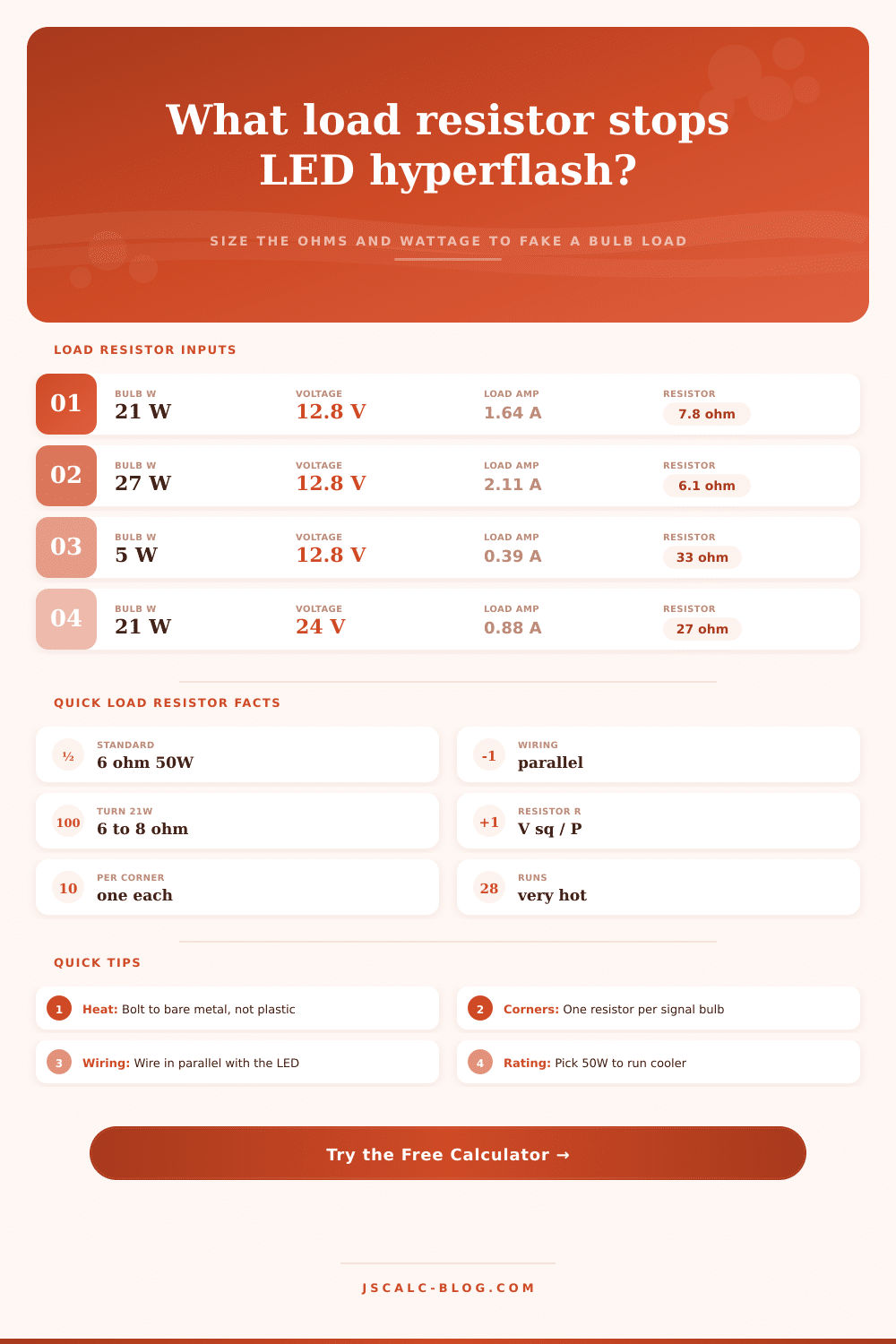
| 21 W | 12.8 V | 1.64 A | 7.8 Ω | 21.0 W | 50 W |
| 27 W | 12.8 V | 2.11 A | 6.1 Ω | 27.0 W | 50 W |
| 21 W | 13.8 V | 1.52 A | 9.1 Ω | 21.0 W | 50 W |
| 21 W | 24.0 V | 0.88 A | 27.4 Ω | 21.0 W | 50 W |
| 27 W | 24.0 V | 1.13 A | 21.3 Ω | 27.0 W | 50 W |
Higher system voltage means the same wattage needs a larger resistor because current falls, yet the heat produced stays close to the original bulb wattage.
⚙Full Formula Breakdown
📋Wattage Rating Safety Guide
| Dissipated Heat | Min Rating (2×) | Cooler Choice | Notes |
|---|---|---|---|
| Up to 5 W | 10 W | 25 W | Markers, small bulbs |
| 5 to 10 W | 25 W | 50 W | Running lights |
| 10 to 21 W | 50 W | 50 W finned | Turn signals |
| 21 to 27 W | 50 W | 100 W | Brake, reverse |
| Over 27 W | 100 W | 2 × 50 W | Dual or high draw |
Aluminum-clad load resistors reach 150°C or more in normal use, so the wattage rating is about survival, not comfort.
🔥Load Resistor Tips
So what? Well, you go change all your old incandescent bulbs for LED lights and now all the blinkers is blinking fast. It is boring. It is distracting, and most importantly, it is illegal in a lot of locations. Why does that happen? Why do folks ends up with flashing light that act like a disco ball? Because newbies don’t understand how older electrical systems work.
How did it know that a circuit was on? By drawing a certain amount of current. What did those incandescent bulbs did when they were drawing current? They generated heat. A lot of heat. Waste heat. Heat was the signal the flasher module was waiting for to maintain its regular rhythm. Then along came these efficient bulb called LEDs. Now the vehicle computer detect the lack of resistance and believes a bulb must be blown. Time to let you know it’s not working right so it starts blinking like crazy.
How to Stop Fast Blinking LED Lights
How does it work? It fools the system into believing there’s still an old load in place. You add a resistor sized to draw just enough additional current to make flasher module happy without illuminating any new bulbs. There’s a math problem but no guessing required: This calculator here does the work for your specific car. It figures everything out based off the wattage of the bulb you replaced, the current consumed by the new LEDs (a tiny bit), and the voltage of the entire system.
That last one is why most folks miss. They think their LED draws zero amps when really it draws less than that. But if you size too large, you’re wasting power and creating heat inside the tail light assembly or down under the dashboard. If you size too small, you end up…hyperflashing. The limiting factor here is heat. Resistors limit the flow of electrons and the limited flow generate heat. Putting in an undersized resistor (i.e. Lower than rated wattage) will lead to melted plastic parts around the resistor or burnt out resistors themselfs. That’s why safety margin is so important.
So how does the calculator work? In general, a typical twenty-one-watt turn signal bulb consume about one and a half amps. You want your resistor to generate close to that level of heat to fake the load. But if you purchase a component with a 10-watt rating, it’s going to get hot pretty fast when used consistantly. With this calculator, you can choose a size/rating that is big enough to fit where needed but not so large that it gets too hot. Going up twice what the calculation suggest makes for something comfy and long-lasting.
But mounting the parts is only part of what matters. They has to go where they can do their job without issue. Electrical tape and your wiring harness aren’t going to work. That’s just asking for frustration and a visit to the repair shop. A high wattage resistor have a body made out of metal and that body must be touching some sort of bare sheet metal to serve as a heatsink. So if you’re bolting it down to the floor, make sure you are not doing so to painted steel. It doesn’t conduct heat nearly as well than aluminum does.
Also make sure you don’t get it trapped between two pieces of plastic. You’re insulating it then with its own heat output. That will cause hot spots which may degrade surrounding insulation after months on the road. Half the fight is finding a piece of grounded metal around your dash or under the tail light.
While resistors can be used as a means of solving hyperflash, there are alternatives. Some new vehicles uses smart relays that sense voltage drop instead of sensing current draw. Because the module doesn’t care about how small of an amount of current the LEDs consume, it keeps its steady blink rate automatically. Adding a resistor would of served no purpose and be wasteful if you have one of these modules. Many cars today are still equipped with basic electronic or thermal flashers, and any classic car work this way too. For these, a resistor is always the best method.
This is because it does not change the wiring harness at all, but just mimics the physics of the original bulb. It’s all about transparency. You want it working just like the engineer who designed it, but you want it lasting longer and wasting less energy. Matching the load perfectly takes away the quick flash without running any risk of overheating. It is a simple tradeoff between efficiency (heat) and convenience.
And then once you have everything wired up correctly (resistor in parallel with the LED), bolted down tightly and mounted, the system levels out. Nobody knows it’s there. Now your LEDs will last much longer, the check engine light won’t come on, and the blink returns to a normal pace. Worth spending a few minutes figuring it out and taking care to mount furnitures properly, right?