Capacitor Voltage Rating Margin Calculator
Check whether a capacitor has safe voltage headroom for your circuit. Enter the applied working voltage and the part rated voltage, pick the dielectric type and temperature, and get the voltage margin percent, the headroom in volts, the minimum recommended rated voltage, and a clear pass or fail verdict based on real derating rules.
📌Real Design Presets
🔌Capacitor and Circuit Inputs
Steady DC bias the capacitor actually sees in circuit.
The voltage printed on the part datasheet.
Sets the baseline recommended derating factor.
Higher temperature tightens the safe voltage further.
Optional. Leave blank to use the dielectric default.
Added to applied voltage for the true peak stress.
🔢Derating Snapshot
📋Applied vs Rated Margin Examples
| Applied V | Rated V | Headroom | Margin % | Reads As |
|---|---|---|---|---|
| 5 V | 6.3 V | 1.3 V | 21% | Tight |
| 3.3 V | 6.3 V | 3.0 V | 48% | Good |
| 12 V | 25 V | 13 V | 52% | Comfortable |
| 5 V | 16 V | 11 V | 69% | Very safe |
| 3.3 V | 10 V | 6.7 V | 67% | Very safe |
| 24 V | 50 V | 26 V | 52% | Comfortable |
| 48 V | 63 V | 15 V | 24% | Tight |
| 1.8 V | 4 V | 2.2 V | 55% | Comfortable |
📊Dielectric Derating and Standard Voltage Grid
| Dielectric | Recommended Derate | Usable at 25V Rated | Common Standard Ratings | Why the Margin |
|---|---|---|---|---|
| Aluminum electrolytic | 80% max working | 20 V | 6.3, 10, 16, 25, 35, 50 V | Ripple heat and wear-out |
| Tantalum (solid) | 50% max working | 12.5 V | 4, 6.3, 10, 16, 25, 35 V | Inrush surge failure risk |
| Polymer tantalum | 60% max working | 15 V | 2.5, 4, 6.3, 10, 16, 25 V | Better surge than solid |
| Ceramic X7R / X5R | 50% max working | 12.5 V | 6.3, 10, 16, 25, 50 V | DC bias loses capacitance |
| Ceramic C0G / NP0 | 60% max working | 15 V | 16, 25, 50, 100 V | Stable but still derate |
| Film polypropylene | 55% max working | 13.75 V | 50, 100, 250, 400, 630 V | Corona and dV/dt stress |
| Film polyester | 50% max working | 12.5 V | 50, 63, 100, 250, 400 V | Lower field strength margin |
🌡Temperature Derating Guidance
| Operating Temp | Extra Voltage Derate | Effect on 25V Part | Typical Case |
|---|---|---|---|
| Up to 45 C | None | Full derated limit | Cool enclosure |
| 45 to 70 C | 5% tighter | ~19 V aluminum | Sealed board |
| 70 to 85 C | 10% tighter | ~18 V aluminum | Near regulators |
| 85 to 105 C | 20% tighter | ~16 V aluminum | Automotive hot spot |
| Above 105 C | Use 125 C part | Check datasheet curve | Under-hood power |
| Below 0 C | Watch ESR rise | Voltage OK, ESR up | Cold start |
⚙Formula Breakdown
💡Practical Derating Tips
The capacitor voltage rating margin calculator give you confidence to know whether or not a cap is capable of handling its true working voltage. Just because it passes an initial test doesn’t mean it won’t fail in the field due to running too near its max limit.
Simply enter your operating temp, dielectric type, datasheet rated voltage, and applied working voltage. You get back minimum recommended rated voltage, headroom in volts, percent voltage margin (a passing or failing verdict), and even the capacitor capacity value for good measure. It ensures reliability and safe voltage headroom, not just a check of capacitance value.
How the Voltage Margin Calculator Works
All capacitors has rated voltages, yet using a part at its rated voltage gets you in trouble sooner then later. Rated voltage is NOT the recommended operating condition of the part; it is a maximum. Add to this ripple, transients, hot operating conditions, part age. And those factors all eat into the theoretical margin. This is where derating come into play: keeping a component under its maximum rating such that real world stressors don’t knock it over the edge.
Having some amount of voltage margin ensures your circuit will last longer, which means fewer returns from the field. It also helps your circuit have fewer issues and stay protected from any surge event. Because the datasheets won’t give you those numbers, you check the margins prior to stuffing boards.
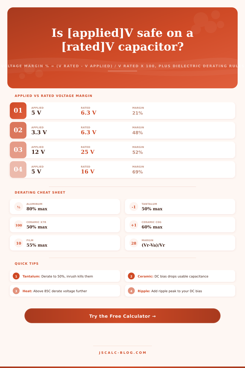
The results are driven by two simple equations. The voltage margin percent equation is: (rated voltage… Applied voltage) / rated voltage x 100. The headroom equation is: Rated voltage, applied voltage (in volts). For example, a 5-volt rail on a 16-volt capacitor provides 11 volts of headroom with a 69% margin, while the same 5-volt rail on a 6.3-volt cap provide just 1.3 volts of headroom and approximately a 21% margin, which is tight.
Once you enter your numbers into the calculator, it do all the math for you. You will have no more errors from dividing manualy at 2am during that late night design review.
This is where most designs go wrong, but not all families of capacitors need the same margin. For example, aluminum electrolytic caps can gradualy wear out their electrolyte and overheat due to ripple current. Because of this, they are typically used to about 80% of their rating. Film caps must be protected from high dV/dt stress and corona, so they’re commonly kept around 50 to 60%. Ceramic caps such as X5R and X7R also tend toward high dC bias, which causes loss of marked capacitance. Because there is also a desire for some safety factor (reliability), they should be operated around 50%. The more stable ceramic types like C0G and NP0 handle about 60% and do better. Tantalum caps wants the biggest cushion, typically 50% or less; as they can fail short with little warning after taking an inrush of turn-on current.
To do this, the calculator transforms the derating rule directly into a number that lets you pick a specific part. Apply the derating factor to your applied voltage, and it’s the minimum rated voltage for the part. For example, if you apply 3.3 volts to a tantalum rated at 50%, the minimum rated voltage is 6.6 volts. You’d pick a standard 10-volt part instead of a 6.3-volt one. It reverses the question: you don’t guess “is this part OK?”, instead you know exactly what the minimum rated voltage for your design must be, and then you round up to the next standard part value.
Higher temps tighten the acceptable range. Beyond the baseline for the dielectric type, most capacitors requires more voltage reduction as their operating temp rises. You can select from one of several ranges of operating temperatures and the tool will add another reduction to that. It reduces it another 5 percent at temps between 45 and 70 degrees C, and then up to 20 percent tighter around a typical hot spot of 85 to 105 degrees (common in dense power supplies and cars). The total derating shown in the breakdown as the effective derating factor combine both the dielectric guideline and the thermal penalty. So the judgment is not just based off an ideal room-temp scenario but also how warm it actually gets.
Each check has four result cards summarizing results. The verdict card indicates if the design passed (PASS), was marginal (MARGINAL), or outright failed (FAIL). This depend on how close the peak stress is to being within the derated limit. The ripple will ride atop the lower level DC bias, so the tool will add the peak ripple to the applied voltage and compare to the limit. A design that is fine based off average DC may get flagged if you include the peak ripple.
The margin card indicates the percentage of available voltage which goes unused. The headroom card indicates the surplus volts. The min rated card provides the name of the lowest rated voltage that meets the rule. Finally, the breakdown panel lists all numbers used to trace the logic and support decisions during a design review.
A circuit designer can improve his circuit’s reliability by adding voltage margin for pennies per part, compared to upgrading all his parts to next-higher voltage rating. Multiply the margin formula by a dielectric-derate factor and add a temperature penalty. Here is a calculator that helps you select the right parts for years of reliable service despite heat, surges, and ripples.
First, the calculator is pre-set. Then, you enter your rated and applied voltages, temperature, and dielectric. Finally, the verdict comes back. From a low-power sensor board to a car module to a power supply: check voltage margin before layout, so no expensive failures end up on your bill of materials in the future. Better to spend the money now on margin, then debug silence later.