Capacitor Code to Farad Calculator
Decode the printed 3-digit EIA number on a ceramic or film capacitor into real capacitance. The value in pF equals the first two digits multiplied by ten raised to the third digit, then convert down to nF and uF, apply the tolerance letter for a min and max range, or reverse a known value straight back into its code.
⚡Choose a Mode
📌Common Capacitor Presets
🔢Capacitor Markings
The bold number stamped on the body. Third digit is a multiplier.
Enter the value you want to turn into a 3-digit code.
The calculator scales this to pF before encoding.
Chooses which unit the main result card features.
Sets the min and max capacitance range card.
EIA voltage marks appear next to the value code.
Controls rounding on the converted value cards.
📈Decoding Snapshot
📋Common 3-Digit Code Values
| Code | Digits x Multiplier | Value pF | Reads As |
|---|---|---|---|
| 100 | 10 x 10^0 | 10 pF | 10 pF |
| 101 | 10 x 10^1 | 100 pF | 100 pF |
| 102 | 10 x 10^2 | 1000 pF | 1 nF |
| 103 | 10 x 10^3 | 10000 pF | 10 nF |
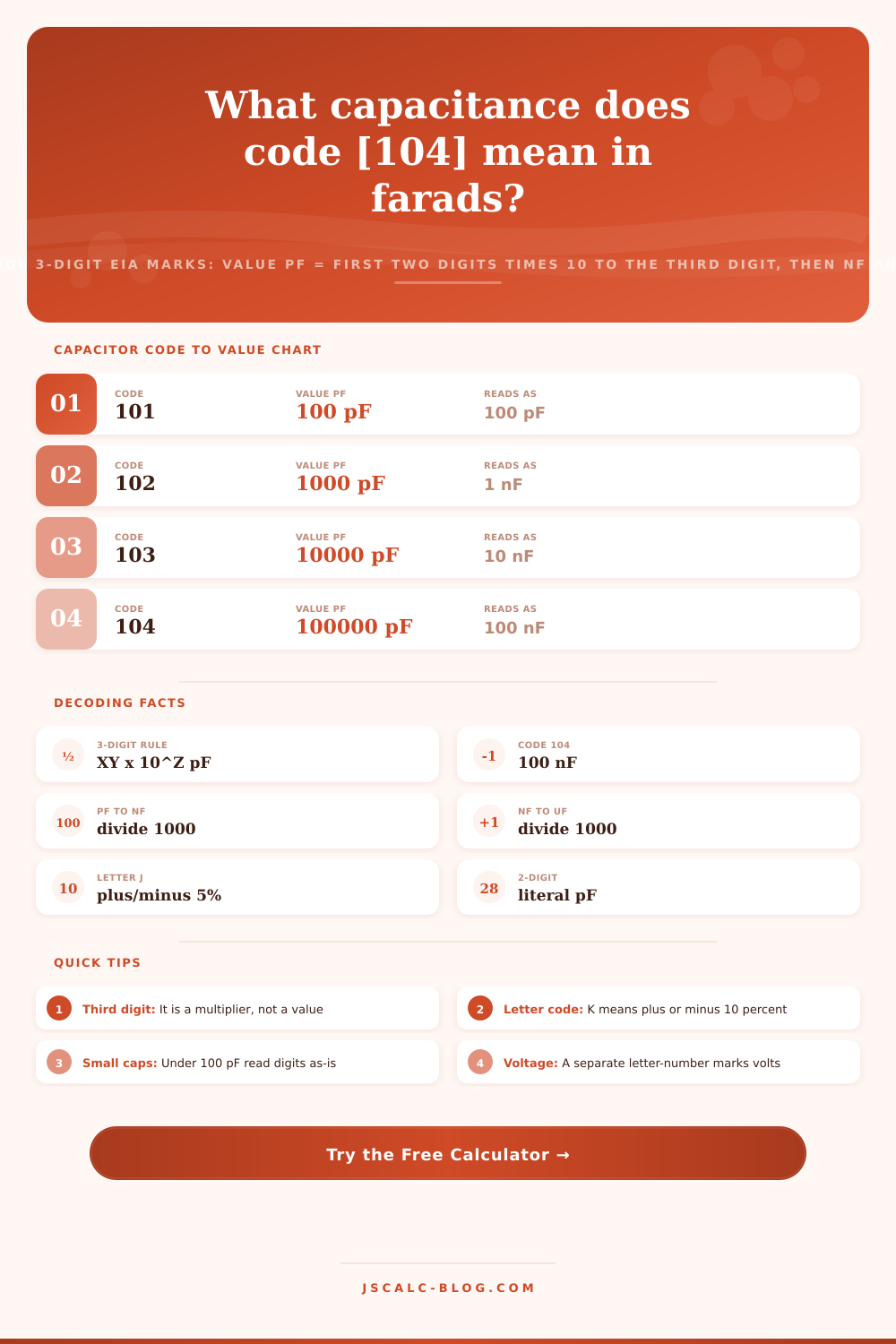
| 104 | 10 x 10^4 | 100000 pF | 100 nF |
| 105 | 10 x 10^5 | 1000000 pF | 1 uF |
| 106 | 10 x 10^6 | 10000000 pF | 10 uF |
| 473 | 47 x 10^3 | 47000 pF | 47 nF |
📏Tolerance Letter Codes
| Letter | Tolerance | Type | Typical Use |
|---|---|---|---|
| B | plus/minus 0.1 pF | Absolute | Tiny RF trimmers |
| C | plus/minus 0.25 pF | Absolute | Precision timing |
| D | plus/minus 0.5 pF | Absolute | Small NPO parts |
| F | plus/minus 1% | Percent | Filter networks |
| G | plus/minus 2% | Percent | Oscillators |
| J | plus/minus 5% | Percent | General film caps |
| K | plus/minus 10% | Percent | Ceramic decoupling |
| M | plus/minus 20% | Percent | Bulk bypass |
🔌EIA Voltage Code Chart
| Voltage Code | Rated Volts | Class | Note |
|---|---|---|---|
| 1H | 50 V | Low | Most small ceramics |
| 2A | 100 V | Low | Signal coupling |
| 2D | 200 V | Mid | Film snubbers |
| 2E | 250 V | Mid | Mains class X2 |
| 2G | 400 V | High | Power supplies |
| 2J | 630 V | High | High voltage film |
🗃Code to pF, nF and uF Comparison Grid
| Code | Value pF | Value nF | Value uF | Reads As | Common Role |
|---|---|---|---|---|---|
| 100 | 10 pF | 0.01 nF | 0.00001 uF | 10 pF | RF tuning |
| 101 | 100 pF | 0.1 nF | 0.0001 uF | 100 pF | Timing |
| 102 | 1000 pF | 1 nF | 0.001 uF | 1 nF | Snubber |
| 103 | 10000 pF | 10 nF | 0.01 uF | 10 nF | Bypass |
| 104 | 100000 pF | 100 nF | 0.1 uF | 100 nF | Decoupling |
| 105 | 1000000 pF | 1000 nF | 1 uF | 1 uF | Coupling |
| 220 | 22 pF | 0.022 nF | 0.000022 uF | 22 pF | Crystal load |
| 221 | 220 pF | 0.22 nF | 0.00022 uF | 220 pF | RF filter |
| 222 | 2200 pF | 2.2 nF | 0.0022 uF | 2.2 nF | Feedback |
| 223 | 22000 pF | 22 nF | 0.022 uF | 22 nF | Film audio |
| 224 | 220000 pF | 220 nF | 0.22 uF | 0.22 uF | Bulk bypass |
| 471 | 470 pF | 0.47 nF | 0.00047 uF | 470 pF | NPO timing |
⚙Formula Breakdown
💡Capacitor Reading Tips
You frequently see a small number etched onto those little ceramic caps. Often it’s something like 104, or maybe 223, or 471. They don’t normaly just print the actual value in farads. Rather, they do it with a clever shorthand three digit code.
This calculator will take that marking and convert it into an actual capacitance value. It will be displayed in microfarads, nanofarads and even picofarads. You can flip it around as well to convert existing value into the code used for your part bins.
How to Read Capacitor Codes
That’s it, the basic rule. The first two digits of the three-digit code form a number. Third digit is power-of-ten multiplier. Result will be in picofarads.
Let’s look at an example, say the code 104. So the first two numbers makes a number of 10. The third digit is a 4. You multiply by ten to the power of four. That’s 10000. Ten times 10000 is 100000 pF. So there’s your conversion with any and all codes from little ones like 100 to big ones like 106.
It takes up less room on these tiny components. But each time you check a part you have to do a bit of mental math. The code uses their native unit, picofarads. Sometimes you’ll see microfarads and nanofarads used in schematics and from suppliers.
The units shifts using powers of ten. To convert from picofarads, divide by 1000 for nanofarads. Divide by one million for microfarads. So 100000 pF = 100 nF. It is also equal to 0.1 uF. That’s where the confusion with a 104 capacitor being referred to as either 0.1 uF or 100 nF comes from.
The calculator will automaticly adjust for those shifts. You don’t need to manually adjust any decimal points.
That’s not to say all capacitors are coded as three digits. If they’re very small, they may only be two digits long. And if it’s only two digits, then there’s no multiplier. It’s literal that many picofarads. So if you see a component labeled as 47, it’s exactly that: 47 pF.
Don’t assume all capacitors uses a third digit when they don’t; doing so will result in an exaggeration of the value. For two-digit entries, the tool uses literal reading by default. A load capacitor on a crystal marked 22 remains 22 pF. Exaggerating the value can affect circuit timing and lead to confusion between a literal versus a multiplier code.
There’s another letter that follows the number code on many capacitors. The letter indicates tolerance, which is how far you are allowed to be from the nominal value. Commonly used are percent grades. F = +/- 1 percent. G = +/- 2 percent. J = +/- 5 percent. K = +/- 10 percent. M = +/- 20 percent.
Some parts use absolute values in picofarads. B = 0.1 pF. C = 0.25 pF. D = 0.5 pF. And then there’s the asymmetric Z grade, meaning +80 and -20 percent.
The calculator allows you to input the tolerance letter. It will tell you the low and high capacitances. That’s important for filter and timing circuits. A loose capacitor can move cutoff frequency too far.
The inverse case also happens. We need 22 nF; we want to know what that looks like on the component. Change the tool to go from value-to-code. Enter it, and select the units. It spits out three digit code.
It’s similar to the forward process. Convert the value to picofarads. Take only the first two significant figures (the XY digits). Let the rest of the zeroes determines the multiplier Z. In this example, 22 nF is 22000 pF. So the XY is 22, with a multiplier of 3. That’s the code: 223.
Reverse decoding can be useful when managing an inventory. This connects the theory side to the parts bin side.
Small voltage codes appear on some capacitors. They’re usually a digit-letter pair, such as 1H or 2G. That information comes from an EIA table. 1H = 50 volts. 2A = 100 volts. 2D = 200 volts. 2J = 630 volts.
Capacitance doesn’t vary based on voltage. But it makes all the difference when it comes to reliability and safety. Running over-voltage will kill the part immedately. With the voltage mark decoded along with value in the calculator, you can be sure your replacement has enough oomph for the task.
There is an easy mistake made in capacitor reading: confusing 104 with actual 104 pF, which would mean it’s off by a factor of a thousand! That will trash a power rail or an oscillator. Having a specific lookup tool removes this possibility. Seconds later, you have a reliable readout and can get back to building instead of guessing.