Cache Size Calculator
Model how a set-associative cache is organized: split a memory address into tag, index, and offset bits, work out the number of sets from cache size divided by line size and associativity, and size the real SRAM by adding valid, dirty, tag, and replacement overhead bits to every line.
🎯Real Cache Organization Presets
📝Cache Organization Inputs
Total address bits split into tag, index, and offset.
The tool derives the other value for you.
Data capacity only, overhead is added separately.
Used when size input mode is total cache size.
A power of two, e.g. 32, 64, or 128 bytes.
Ways per set; fully associative means a single set.
Used when size input mode is number of sets.
Metadata bits stored per line to pick a victim.
Write-back keeps 1 dirty bit per line; each line has 1 valid bit.
Controls the units on the overhead result card.
🔢Organization Snapshot
📋Cache Address Split Examples
| Cache Size | Line | Offset Bits | Lines | Reads As |
|---|---|---|---|---|
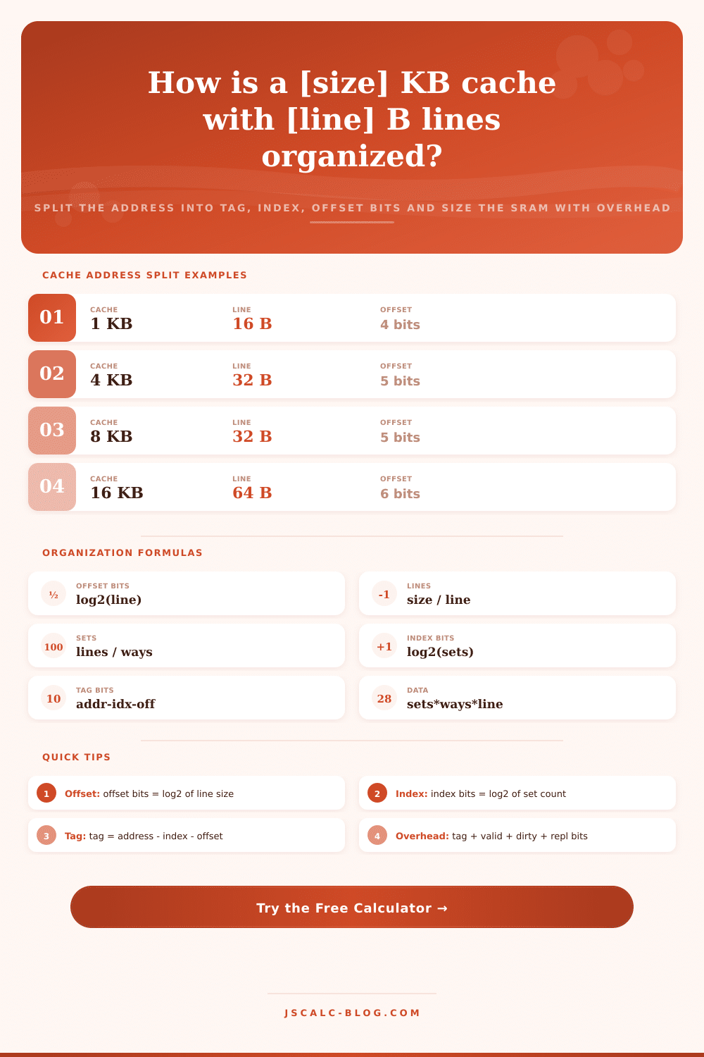
| 1 KB | 16 B | 4 | 64 | Tiny lookup |
| 4 KB | 32 B | 5 | 128 | Micro cache |
| 8 KB | 32 B | 5 | 256 | Small L1 |
| 16 KB | 64 B | 6 | 256 | Classic L1 |
| 32 KB | 64 B | 6 | 512 | Modern L1 |
| 64 KB | 64 B | 6 | 1024 | Large L1 |
| 256 KB | 64 B | 6 | 4096 | Per-core L2 |
| 1 MB | 64 B | 6 | 16384 | Big L2 |
| 8 MB | 64 B | 6 | 131072 | Shared L3 |
📈Associativity and Set Count
| Associativity | Ways | 32 KB / 64 B Sets | Index Bits | Trade-off |
|---|---|---|---|---|
| Direct-mapped | 1 | 512 | 9 | Fastest, most conflict |
| 2-way | 2 | 256 | 8 | Simple, few conflicts |
| 4-way | 4 | 128 | 7 | Common L1 balance |
| 8-way | 8 | 64 | 6 | Typical modern L1 |
| 16-way | 16 | 32 | 5 | Dense L2 and L3 |
| Fully assoc | 512 | 1 | 0 | No conflict, costly |
📊Overhead Bits Per Line
| Metadata | Bits | Purpose | When Present |
|---|---|---|---|
| Valid bit | 1 | Line holds real data | Always |
| Dirty bit | 1 | Line was written | Write-back only |
| Tag bits | addr - idx - off | Identify the block | Always |
| Replacement bits | 0 to 4 | Pick victim line | Set-associative |
| Coherence state | 2 to 3 | MESI protocol | Multicore SMP |
| ECC / parity | 7 to 8 | Error correction | Server caches |
🖥Typical CPU Cache Comparison Grid
| Cache Level | Size | Line | Associativity | Sets | Offset Bits | Index Bits |
|---|---|---|---|---|---|---|
| L1 data | 32 KB | 64 B | 8-way | 64 | 6 | 6 |
| L1 instruction | 32 KB | 64 B | 8-way | 64 | 6 | 6 |
| L1 data wide | 48 KB | 64 B | 12-way | 64 | 6 | 6 |
| L2 per core | 256 KB | 64 B | 8-way | 512 | 6 | 9 |
| L2 large | 1 MB | 64 B | 16-way | 1024 | 6 | 10 |
| L2 server | 2 MB | 64 B | 16-way | 2048 | 6 | 11 |
| L3 shared | 8 MB | 64 B | 16-way | 8192 | 6 | 13 |
| L3 desktop | 16 MB | 64 B | 16-way | 16384 | 6 | 14 |
| L3 server | 32 MB | 64 B | 16-way | 32768 | 6 | 15 |
| Direct-mapped | 16 KB | 64 B | 1-way | 256 | 6 | 8 |
⚙Formula Breakdown
💡Cache Sizing Tips
Memory isn’t just a linear array of bytes that the processor reads. It’s a hierarchy of caches, a series of decision on whether to satisfy a request with speedy silicon or stall until RAM arrives. To understand that hierarchy, you must look at an address breakdown. How was raw address width divided? It is divided into what parts, tags, indices, and offsets? It’s done mechanically to allow the whole thing to be looked up in a single clock cycle, no need to scan each line. See where the bottlenecks are if you know how those bits gets allocated.
The block offset comprise the bottom bits of an address. They don’t help locate the data, but they select which byte from a line is provided when the cache delivers it. For a sixty-four-byte line, you need six bits for the block offset: 2^6 = 64. Note that this figure doesn’t depend on size of the whole cache, just how it’s designed to work.
How Memory Bits Work
Next are the index bits (the middle bits), which is used to locate somewhere inside memory array. A wider index field mean there are more sets, whereas fewer sets mean fewer index bits. That creates a trade-off between how much cache can fit in an area and search speed.
What happens to the rest of high bits? That’s the tag, and that’s where conflict comes into play. To check whether the data at current address belongs in the cache, the memory compares those tags you’re storing there against new address. More bits mean more space wasted on each line, so the cache will hold fewer lines, but it’ll also let you get away with higher associativity.
The way your CPU puts a block into a set determine how many ways you can put it: higher associativity decreases conflict misses. Two addresses mapping onto the same slot is bad news as direct-mapped caches do not have any flexibility. In contrast, fully associative caches is infinitely flexible but expensive (in both area and power) since they has to compare all lines. Most set-associative caches falls somewhere in between, balancing ease of hardware implementation and hits.
That’s because the cache size advertised for most chips doesn’t count any overhead for metadata. You don’t get exactly thirty-two kilobytes of silicon when you have a thirty-two-kilobyte L1 cache. There are tag bits for each line. There is a valid bit to say whether it’s present or not. There is a dirty bit if you use a write-back policy. Finally, there are bits to record replacement state to evict lines from the cache.
The sum of these hidden costs gets added up by the calculator over all the lines in the array. In today’s cores, it adds ten to fifteen percent to total SRAM cost on-chip. This additional storage burns static power and takes up space on the die. Try running through various presets to observe changes in associativity on your bit budget.
Higher ways shrinks the index while expanding the tag (which requires a slightly more moddern address decoder), which decreases the chance of thrashing across nearby memory locations. Larger line sizes increase spatial locality; however, it will waste bandwidth when you need just a few bytes. The tool breaks this down into two bars. One shows how many bits go towards identifying the block. The other shows how to find the set within that block’s allocated address space.
The idea is that we want maximum hit rate and minimum latency given our physical constraints. More bits in the tag mean fewer bits in the index; more bits in the index mean fewer bits in the tag. If you get it wrong, your code will wait around for memory; if you get it right, your code will run smoothly. Begin with a default preset, then vary one thing at a time and see how the system reacts.
What the silicon sees tells you the numbers. Performance decisions happens here. You should of checked the bit budget first. It actualy makes a big diffrence in the end. All this furnitures for data is expensive. Making sure those bits are placed comfortabley is key, more then just luck. The way the address width was divided based off the tag is important. If you miss one of the bit, it dissapears from your budget.