12 Gauge Wire Voltage Drop Calculator
Find voltage drop, percent loss, voltage at the load, and the longest safe run for a 12 AWG copper or aluminum circuit using the round-trip 2 × L × I × R formula and NEC drop targets.
🔌Real 12 AWG Wiring Presets
📝Circuit Inputs
12 AWG ampacity is 20 A at 60/75°C.
Distance one direction; the tool doubles it for the return conductor.
Higher wire temperature raises resistance and drop.
🔢Formula Snapshot
📊12 AWG Specs: Copper vs Aluminum
| Property | Copper 12 AWG | Aluminum 12 AWG | Notes |
|---|---|---|---|
| Resistance | 1.588 Ω/1000ft | 1.98 Ω/1000ft | At 20°C, DC / 60Hz |
| Ohms per foot | 0.001588 Ω | 0.00198 Ω | Used in the formula |
| Ampacity (60°C) | 20 A | 15 A | NEC Table 310.16 |
| Ampacity (75°C) | 20 A | 15 A | Common breaker limit |
| Diameter | 0.0808 in | 0.0808 in | Same nominal size |
| Area | 6530 cmil | 6530 cmil | Circular mils |
| Typical use | 20A outlets, tools | Feeders, older wiring | Al needs anti-oxidant |
📏Length vs Percent Drop (12 AWG Copper)
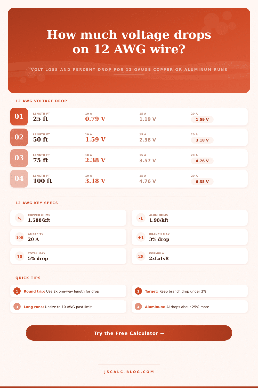
| One-Way Length | Drop at 10 A | Drop at 15 A | Drop at 20 A | % at 20 A (120 V) |
|---|---|---|---|---|
| 25 ft | 0.79 V | 1.19 V | 1.59 V | 1.32% |
| 50 ft | 1.59 V | 2.38 V | 3.18 V | 2.65% |
| 75 ft | 2.38 V | 3.57 V | 4.76 V | 3.97% |
| 100 ft | 3.18 V | 4.76 V | 6.35 V | 5.29% |
| 125 ft | 3.97 V | 5.96 V | 7.94 V | 6.62% |
| 150 ft | 4.76 V | 7.15 V | 9.53 V | 7.94% |
📐Max One-Way Length for 3% Drop (12 AWG Copper)
| Current | 12 V DC | 24 V DC | 120 V | 240 V |
|---|---|---|---|---|
| 5 A | 22.7 ft | 45.3 ft | 226.7 ft | 453.4 ft |
| 10 A | 11.3 ft | 22.7 ft | 113.4 ft | 226.7 ft |
| 15 A | 7.6 ft | 15.1 ft | 75.6 ft | 151.1 ft |
| 20 A | 5.7 ft | 11.3 ft | 56.7 ft | 113.4 ft |
🗂NEC Voltage Drop Guidelines
| Circuit Part | Recommended Max | At 120 V | At 240 V | Why It Matters |
|---|---|---|---|---|
| Branch circuit | 3% | 3.6 V | 7.2 V | Outlet and device supply |
| Feeder only | 3% | 3.6 V | 7.2 V | Panel to subpanel |
| Feeder + branch | 5% | 6.0 V | 12.0 V | Total combined loss |
| Sensitive load | 2% | 2.4 V | 4.8 V | Electronics, motors |
| Absolute upper | 5% | 6.0 V | 12.0 V | NEC informational note |
⚙Full Formula Breakdown
🗃12 AWG Voltage Drop Comparison Grid
| One-Way Length | Vdrop 10 A | Vdrop 15 A | Vdrop 20 A | % 15 A (120 V) | Within 3%? |
|---|---|---|---|---|---|
| 10 ft | 0.32 V | 0.48 V | 0.64 V | 0.40% | Yes |
| 25 ft | 0.79 V | 1.19 V | 1.59 V | 0.99% | Yes |
| 40 ft | 1.27 V | 1.91 V | 2.54 V | 1.59% | Yes |
| 50 ft | 1.59 V | 2.38 V | 3.18 V | 1.98% | Yes |
| 60 ft | 1.91 V | 2.86 V | 3.81 V | 2.38% | Yes |
| 75 ft | 2.38 V | 3.57 V | 4.76 V | 2.98% | Yes |
| 80 ft | 2.54 V | 3.81 V | 5.08 V | 3.18% | No |
| 100 ft | 3.18 V | 4.76 V | 6.35 V | 3.97% | No |
| 125 ft | 3.97 V | 5.96 V | 7.94 V | 4.96% | No |
| 150 ft | 4.76 V | 7.15 V | 9.53 V | 5.96% | No |
💡Practical 12 AWG Tips
Your garage just underwent a huge remodel. There are new lights, fresh concrete, and everything else. Time for some trim work so you grab your trusty angle grinder. Plug it in and get to cutting. Half way through your cut, the grinder sputters. Not totally failing mind you, but losing its torque. It’s like thing is on half a tank when trying to cut through whatever you’re cutting into.
No worries, you think. Circuit breaker is good. Nothing tripped or shorted out. There was a voltage drop. Your 12 gauge wire couldn’t provide enough power over that long distance to satisfy the motor.
Why Voltage Drop Matters in DIY Wiring
Voltage drop will kill a lot of do-it-yourself electrical jobs. There’s power at the panel, but by the time it reaches your outlet, there isn’t. Fortunately someone built this really nice calculator for us so we don’t need tables of copper wire or to pull out our slide rules and guess at anything. Plug in how long the run is (one way), what current draw on the circuit will be, and what voltage the source runs off and it does the rest. How much power is being lost in transit is clearly displayed.
But how do you know what numbers to plug into it? Why do those matter? Most people understand electricity as a pipe where water flows through. If there’s lots of pressure in at the beginning, then there should be lots of pressure when it comes out right? Well that isn’t entirely true with electricity. There is a thing called resistance. Each foot of wire represent a little speed bump for flow of electricity. As the current draw increases and as distance increases, more and more energy are wasted in the form of heat instead of actualy performing any kind of task.
And that is what people miss. Sure they properly size the breaker, but do they consider whether or not the wire itself can handle delivering voltage? The default here is 12 gauge, the workhorse of general home circuits. That’s plenty thick for small appliances and most outlets, pulling 20 amps. But there’s a limit. Stretching out a 12 gauge copper line beyond a certain point add up. Resistance increases as well.
The calculator takes that into account with its round-trip formula. Remember current doesn’t simply travel to your device. It has to return. A 50 foot run isn’t really 50 feet of wire working. It’s 100. Double the distance is where many amateur slip up. Their calculators tell them they need 50 feet, yet their tools still dim slightly.
The other option here is to toggle between copper and aluminum. While both will do the job, copper is the gold standard when it comes to resistance. Less resistance means it can gets the same juice over longer distances while dropping less voltage along the way. Switching that selector changes things a lot if you’re dealing with certain feeder requirements or old homes.
Moddern electrical codes include a built in rule: no more than three percent voltage drop on branch circuits. That equates to about 3.6 volts for a normal 120 volt system. Seems low right? And what does it cost you? Starve motors of voltage and they slow down and get hot. Not good. Annoying dim lighting is one thing, dangerous tool overheating is another.
See where the percent drop calculation takes you. Is it safe enough hovering right around the margin or inching closer and closer toward being in trouble? If the reading indicates high percentage… The answer is not typically “just live with it”. Typically you have to upsize your wire from 12 to 10 gauge. 10 gauge wire has less resistance and allows voltage to move farther along before it fades.
And then there’s that thing called the environment. Resistance in wire doesn’t stay constant; as temperature rises, so does the resistance. Running a circuit in your hot attic or jamming one into an overfilled conduit will result in greater resistance compared to same setup in a cool basement. The calculator accounts for this fact of life by adjusting for temperature. It may be a slight consideration, but if you’re contemplating permanent installations (not temporary extension cord jobs), it counts.
You also have the laws of physics working against you. But also distance, temperature, and the nature of materials, each in its own way. If you look at these numbers, take note of the voltage on the load end. This is what your device sees. For example, if you have a high-draw motor or a sensitive electronic device running off a 120 volt supply but it’s only getting 115 volts, you will notice a drop in performance.
Max length output represents a hard stop for your particular configuration. It marks the limit of where you can run and still be above that critical drop threshold. It is boundary marker for planning out your projects.
In short, wiring is all about balance. Use the least expensive wire that will do the job right every time. Twelve gauge is inexpensive and versatile, but it has its limits when it comes to distance. So before you yank that cable from the panel, look up the numbers so that you won’t have an angry light and stuttering tools as a result. You’ll make sure that power leaving the panel has enough juice to reach its final destination and do the very thing you paid for. A little math is well worth the certainty that it will work.